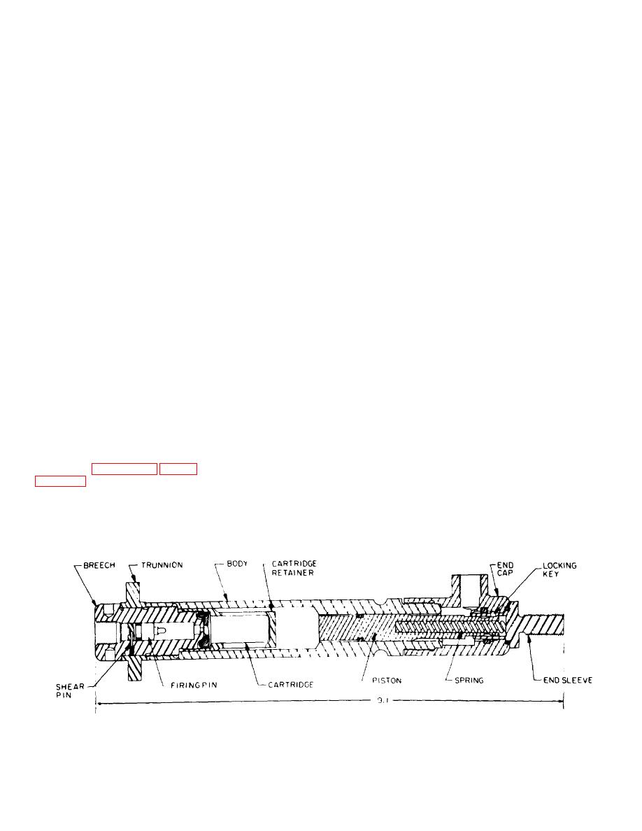
the gas inlet port and exerts pressure on the firing pin.
Bypass require ..............Bypass at end of stroke,
When sufficient pressure is built up behind the firing pin,
ments.
500 psi at end of 4-ft.
the shear pill is sheared and the firing pin is propelled
hose
toward the cartridge, where it strikes the primer. The
Lock requirements ........Initial lock required
primer fires the igniter charge (black powder) which
Thrust
Propel 550-pound weight
ignites the propellant in the cartridge. Propellant gas,
upward through 1.5-
generated by the burning propellant, causes the
inch stroke
cartridge case to rupture. The propellant gas then flows
Structural loads ............800 pounds in tension
into the volume behind the piston. Gas pressure on the
Envelope
Envelope and mounting
piston forces it forward, compressing the spring and
are to remain the same
causing the locking keys through cam action, to move
as those of an earlier
out of the annular groove in the end cap into the piston
thruster, the T3
unlocking groove.
The piston continues to move
Locked-shut .................The thruster shall with-
forward until it contacts the end sleeve. At this point,
stand locked-shut fir-
the piston transmits the force through the end sleeve to
ings without mechani-
the load. As the piston nears the end of its stroke, the
cal failure
O-ring around the piston enters an enlarged section in
No-load ........................The piston shall not
the end cap, permitting propellant gas to escape around
separate from the body
the piston and through the bypass port while the piston
when the thruster is
completes its stroke.
fired without load
73.
First Order Approximations .
a.
Before
72. Component Layout. a. Since the envelope
workhorse models of the thruster can be fabricated,
dimensions are specified, the stroke is short, and the
using the tentative layout already discussed, the
load to be propelled is light, it is expedient to fit the
propellant charge must be estimated so that a cartridge
necessary components into the envelope and then, with
size can be approximated. The pressure needed to
a better knowledge of the volumes involved, estimate
produce the desired thrust, with the selected piston is
the charge.
used to establish the wall thicknesses and other
b. All components of the thruster may be mounted
component dimensions.
on a single longitudinal axis. A typical gas firing
b. The thruster is designed to supply gas at a
mechanism is fitted to the envelope near the gas entry
pressure of 1,000 psi to a 0.062 cubic-inch chamber at
port. A cartridge, the exact size of which is still
the end of 4 feet of hose after moving a 550-pound
undetermined, is placed in front of the firing mechanism.
weight vertically upward for 1 1/2 inches.
A piston is then fitted in the remaining space in the
envelope. A locking mechanism similar to the one
c. The tentative diameter of the piston is 0.50 inch,
described in paragraph 41 (fig. 36) is fitted in the piston.
with a corresponding area of 0.20 square inch. To raise
the 550-pound load, the minimum pressure required is
operates in the following manner: Propellant gas from
2,750 psi.
an initiator enters
Figure 67. Thruster component layout.
84


