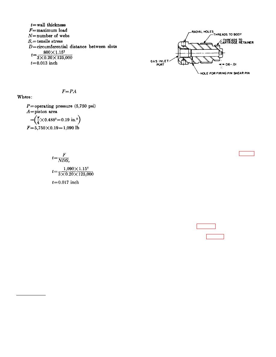
e. The end sleeve may also fail in compression
when the piston is moving the required load. The
Figure 7. Breech for thruster.
maximum compression force (F) due to thrust
is:
the outside of the breech are two sets of threads. The
smaller thread accommodates the cartridge retainer,
and the larger thread accommodates the body of the
thruster.
b. The firing pin is located ahead of the gas inlet
port in a position where it cannot be contacted by the
end of the hosefitting. A hole in the breech, normal to
the longitudinal axis of the device, is provided for the
firing shear pin. A setscrew backs up the shear pin to
retain the pin and to prevent gas leakage.
The minimum thickness for the walls of the sleeve to
withstand the compressive force is calculated in the
80. Firing Mechanism . The firing mechanism consists
same manner as for the tensile force:
of a firing pin and a shear pin. The firing pin (fig. 74) is
a small alloy-steel cylinder with a projection (tip) on one
end and a slot on the other end. A radial shear-pin hole
is located in the body of the firing pin. This hole
accommodates a 0.040-inch-diameter shear pin which
positions and retains the firing pin in the breech prior to
actuation. The slot in the rear face of the firing pin
The walls of the end sleeve are, therefore, made thicker
permits the pin to be turned in the breech during
than 0.017 inch.
assembly to align the shear pin holes in the firing pin
body and the breech. An O-ring on the firing pin
79. Breech. a. The breech (fig. 73) is a steel cylinder
prevents the gas entering the inlet port from escaping
with an axial gas inlet port. The breech houses the firing
past the firing pin. The O-ring is located so that it does
pin and acts as the firing pin guide. The closed end of
not pass over the shear pin hole as the pin is propelled
the breech has a contoured boss to fit the cartridge
forward. The length-to-diameter ratio of the firing pin
head. The firing pin protrusion beyond the face of the
was established at 1.5 (table X) and the travel was
breech is 0.058+0.010 inch. This is the protrusion
designed to produce the required 60 inch-ounces of
permitted by the primer specification. Close tolerances
energy to fire the 72M primer (table IX).
must be established for the forward end of the breech
because: (1) the face of the breech must seat on the
81. Trunnion. a. The trunnion on the thruster is
cartridge head to support it, and (2) the closed end of
similar to that used in the example of the catapult. The
the breech must create the proper spacing for firing pin
trunnion (fig. 75), located between the breech shoulder
protrusion. Four equally spaced radial holes are located
and the end face of the body, is free to rotate a full 360
on the outside diameter to permit the breech to be held
to facilitate mounting the thruster.
with a spanner wrench when assembling the unit. On
b. In designing any trunnion, the pivots must be
located in such a way that there is no free play (side
slake) when the thruster is in the mounting; otherwise,
the pivots will be exposed to bending stresses as well as
† Safety factor.
89


