the bending moment is applied to the outside tube well
lock the block to the inside tube. Near the top of the
below the threaded section, thus avoiding excessive
cylindrical section of the block, two slots, diametrically
stress concentration.
opposite to one another, are provided for the latches. A
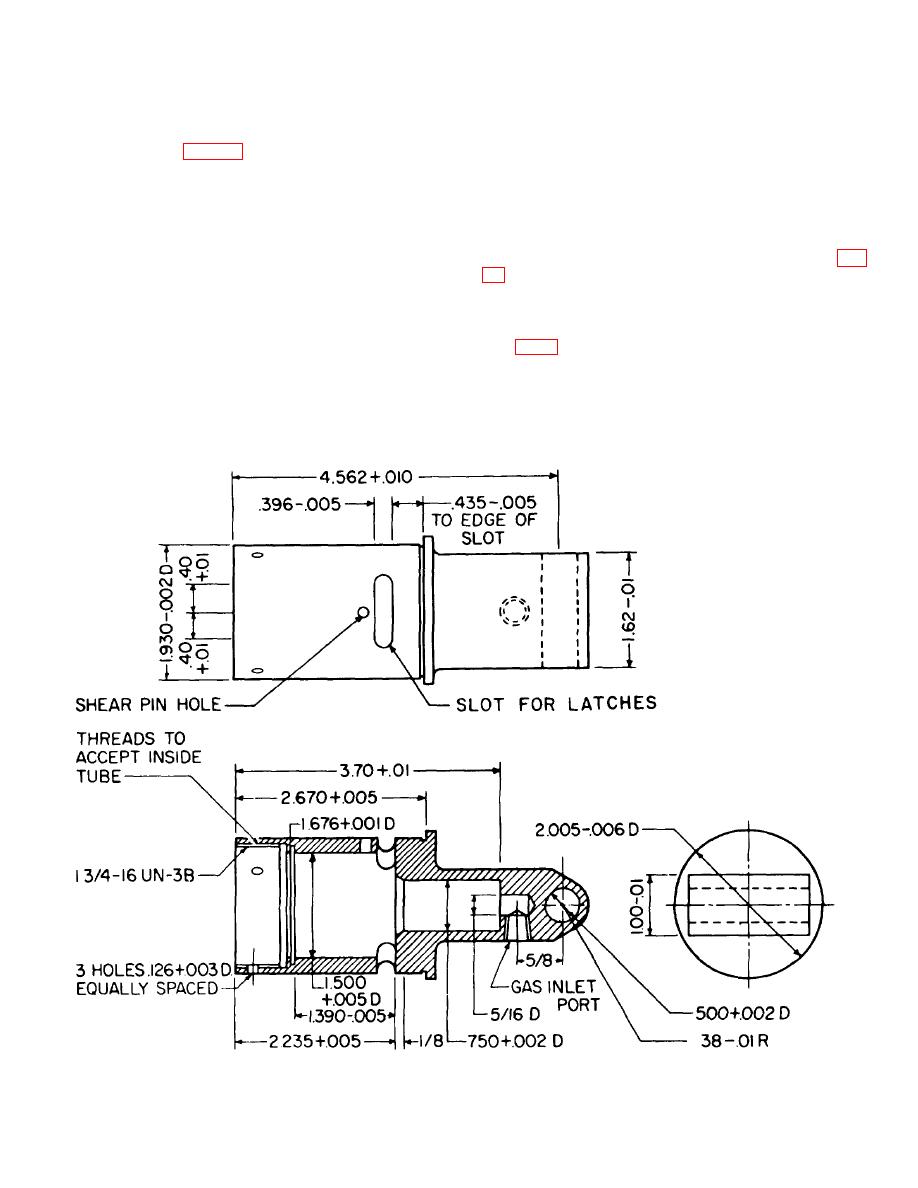
65. Block.
shear-pin hole, just below one of the latch slots, permits
the firing pin to be locked in position. A gas inlet port is
provided in the rectangular portion of the block, and a
houses the firing mechanism and the latches. The block
mounting hole permits the catapult separating parts (the
is cylindrical at one end and rectangular at the other.
block and inside tube) to be attached to the pilot's seat.
The cylindrical section of the block has internal threads
to accommodate the inside tube. The inside tube
b. The block must be strong enough to contain the
houses the cartridge. A polyethylene shock washer is
gas pressure supplied to the firing mechanism contained
installed between the end of the inside tube and the
in the block. The area around the mounting hole (fig.
cartridge shoulder, and the inside tube is then screwed
into the block assembly. Three equally spaced holes
tensile load placed on the mounting.
are provided around the lower portion of the block.
c. The minimum thickness of material in the male
When the inside tube (with cartridge inserted) is
clevis is (0.38-0.01) - (0.250+0.001) inch or 0.119 inch.
screwed into the block, one of the four slots in the tube
(See fig. 6-9.) The area in tension is, therefore:
is aligned with one of the three holes in the block with
every 30of rotation. When the joint is tightened to the
required torque, a ball is inserted in the hole and slot
which are aligned, and the hole is staked (distorted) to
Figure 60. Block for catapult.
79


