prevent motion of the stroking member before firing.
This function is of special importance in devices
operating against tension loads, since the lock prevents
the piston from extending prior to actuation of the
device.
The two locked sections often act as a
structural element, e.g., to hold the pilot seat in its
position in the plane.
Initial locks also prevent
unintentional separation of the device due to tampering,
vibration or dropping.
b. Final locks are required on some devices to
maintain the piston in the end-of-stroke position,
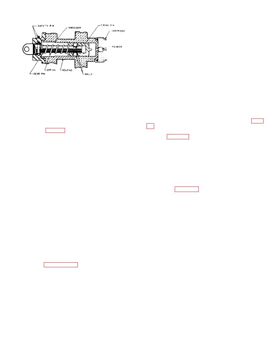
Figure 35. Mechanically operated firing mechanism.
extended or retracted, as the case may be. The final
lock generally is a simple arrangement, consisting of a
(pin) to be disengaged from the firing pin,
snap ring or self locking ball lock which locks into a
and the sear (pin) is withdrawn from the
groove or other depression in the piston.
device. The firing pin then is propelled by
c. While an initial lock requirement may be met by
the compressed spring against the
a simple shear pin or shear ring which locks a piston and
cartridge which contains a percussion
housing together, the problems involved with shear pins
primer.
(covered in this chapter under "Special Problems," para.
(3) The energy required to fire the primer
consideration. A method used in several thrusters is
force and the firing pin travel. The spring
shown in Figure 36. This thruster does not unlock until
is designed to provide several times the
the cartridge fires. When the cartridge fires, gas
all-fire energy of the primer thus providing
pressure forces the piston forward (compressing the
a substantial factor of safety.
spring but not moving the end sleeve) until the four
locking keys drop into a groove in the piston, removing
(4) The selection of spring configurations can
the connection between the housing and the piston. The
best be made by using tables available in
spring keeps the piston in the locked position prior to
spring design handbooks. Such tables
firing. A somewhat similar device is used to lock the
present spring forces and deflection per
tubes of many removers and catapults, except that the
turn for round wire helical springs of
locking keys are released by the firing pin prior to firing
various materials.
the catapult. Figure 37 shows a pair of locking keys
(5) The spring always is kept in a preload
(latches) in position on a firing pin. When gas pressure
position (partially compressed) to insure
is provided behind the firing pin, the pin is propelled
continuous engagement between the
toward the cartridge. As the firing pin moves toward the
spring and the firing pin. This continuous
primer, cam action draws the keys inward, thus freeing
engagement prevents vibration of the
the stroking members.
firing pin when assembled in the device.
d. Design requirements usually list the initial and
Propellant actuated devices are never
final lock requirements from which the size of the
designed with firing pins in the cocked
components involved may be established. The total
position. However, the cocking and firing
shear area and the total area in bearing determine the
of the device is initiated by a single
size of locking keys or locking rings. The emphasis of
operation.
such designs should be on functioning reliability.
(6) The actual procedure followed in
42. Seals. a. Seals in propellant actuated devices
designing a mechanical firing mechanism
perform two important functions: they prevent the entry
may best be seen by referring to
of moisture and dirt during extended storage periods
prior to firing, and they
mechanically
operated
initiator
is
illustrated.
41. Locking Mechanisms. a. Two functional types of
locking mechanisms are used in propellant actuated
devices: initial and final locks. Initial lock mechanisms
41


