where F
67. Locking Mechanism. a. The locking mechanism
consists of two identical steel latches which are located
in a plane perpendicular to the longitudinal axis. The
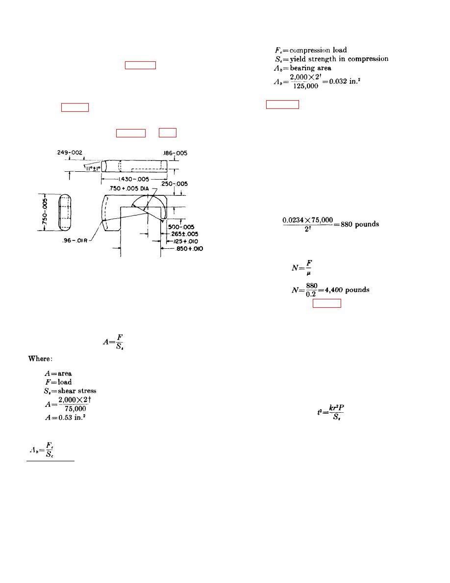
outside face of the latch (fig. 63) has the same
curvature as the inside of the trunnion, and the top edge
of the face is beveled. When assembled, the latches
pass through the slots in the block and extend into the
c. It is apparent from the calculations that the
space between the stop ring and the shoulder in the
latches (fig. 6.3) will be overdesigned and no stress
trunnion (fig. 55), locking the catapult in the closed
problem exists. The width must be made about 3/4 inch
position. The latches are held in a locked position by
to permit the recess of the firing pin to be machined in
the firing pin, which is seated in a circular recess in the
the latch (for locking) and a thickness of 1/4 inch
provides more than ample thickness for machining the
pin is held in place by the shear pin.
locking recess in the side of the key.
d. It is important to note an 11 bevel at the latch
end. This makes extraction of the latches easier and
reduces the load on the small end (tang) of the latch.
e. Using a tang 1/8 by 3/16 inch (1/4-1/16 recess)
provides a 0.0234 in.2 area for shear (each latch). The
force, F, required to shear the tang is there-
fore:
Using a coefficient of friction of 0.2, the perpendicular
load, N, which the latch tangs are capable of moving,
neglecting bending, is:
Figure 63. Locking key for catapult.
b. The latches are designed to hold the tubes in
the closed position when the 2,000-pound tension load is
applied. Since the latches fit into the trunnion and the
stop ring without free play, the latches are in single
alloy-steel cup-shaped section.
The cap contains
shear. Applying a simple stress formula, the area
internal threads and is screwed on the outside tube,
required for the latches is calculated as follows:
closing the tube at the base. Two shallow holes are
drilled in the cap to permit tightening the cap on the
outer tube.
b. The cap may fail in three ways: the end may
blow out, the side may tear at the undercut of the
threads, or the threads may shear out. The strength of
the end of the cap is calculated by using the formula for
stress in a circular plate with fixed edges subjected to a
uniformly distributed load.
Another important consideration is the bearing load of
the latches upon the stop ring.
† A safety factor of 2 is used because this is a structural member.
81


