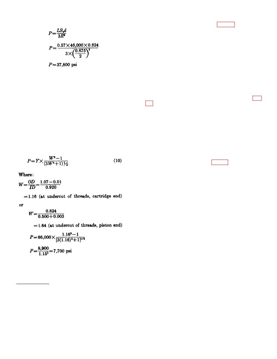
therefore:
aluminum cylinder with internal threads for attaching the
body. A bypass port projects from the end cap normal
to the axis of the thruster. The bypass incorporates a
standard type boss.
Interference and stopping
shoulders, to stop the piston at the end of stroke, are
located ahead of the bypass port. The O-ring seals are
positioned so that the relative motion of the components
will not cause them to pass over any holes or grooves
In the bypass pressure example calculated above for
which could tear the seals and render them ineffective.
the M3A1 thruster, the peak pressure is only 5700 psi;
b. The thinnest section of wall in the end cap not
therefore, the threaded connection will withstand over
only has a larger wall ratio than the body, but also is
six times the estimated peak pressure.
subjected only to the bypass pressure; therefore, it is not
c. The wall strength equation (equation 8)† is used
necessary to calculate the strength of the walls in this
to calculate the maximum pressure (locked-shut) that
component. A 0.000- to 0.003-inch interference fit (fig.
the walls of the body will withstand. When several
sections of wall thickness appear thin, the wall ratio of
kinetic energy of the piston before it strikes the stopping
each section is found, and the smallest wall ratio is used
shoulder in the end cap. Tests must be conducted to
in the calculations.
determine whether the proposed interference fit and
shoulder are capable of stopping the piston without
d. The triaxial load equation can only be used if
causing permanent deformation to the end cap or the
the piston applies the full load longitudinally to the body.
piston.
In this case, the peak pressure, which the body will
contain, may occur before the end of stroke, before a
full longitudinal load could exist; therefore, the biaxial
77. Piston Assembly . a. The piston assembly
equation (which provides the highest stress) is used.
consists of a piston, end sleeve, piston locking spring,
and locking keys. An O-ring is located on the large
outside diameter of the piston (fig. 70) to prevent the
propellant gas from escaping. The stopping shoulder is
located on the piston in front of the O-ring groove and
the diameter of the piston, behind the O-ring is smaller
than the bore of the end cap to permit gas to escape
around it after the O-ring clears the bore of the body.
The initial locking and unlocking surfaces are located on
the outside diameter of the piston at the small end. The
forward 2 inches of the piston are hollow, and the piston
locking spring is inserted in this section.
b. The design of the piston locking spring requires
a force of 20 pounds to be exerted on the piston before
the spring will compress sufficiently to permit the locking
keys to move inward and unlock the piston and end
sleeve. Although the end sleeve is a part of the piston
assembly, it is described with the locking mechanisms
because it contains the locking keys.
c. In designing the piston, the size of the critical
column depends on the area, end conditions, modulus
On the basis of these calculations, it is apparent that the
of elasticity, moment of inertia, and the slenderness
body, as designed, will withstand the maximum pressure
ratio. The ultimate load or the induced stress can be.
developed (5,750 psi).
computed. Much depends on
† This equation may not be used where discontinuities are present.
‡ Safety factor.
86


