A = 1.61 X 0.119 = 0.192 in. 2
Assuming the block will be made of aluminum, the
tension load required to tear the male clevis is:
It is obvious from the above calculation that the design
can easily withstand the 2,000-pound tension load
required; therefore, the male clevis part of the block is
designed more than adequately. Aircrewmen worry less
about the apparent strength of the device when
lightening procedures are not used in this section. The
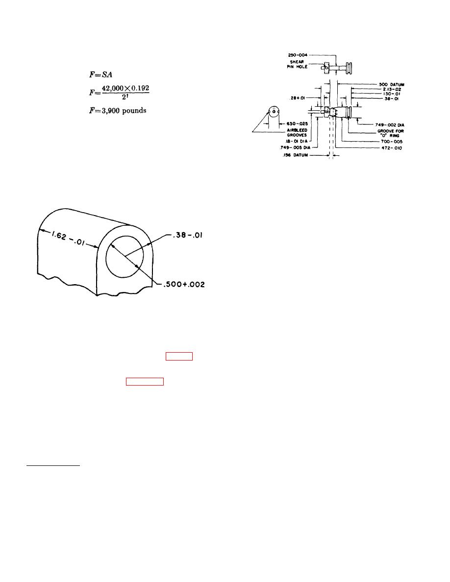
Figure 62. Firing pin for catapult.
walls of the block in the area of the latch slots must be
thick enough to provide sufficient bearing when the
shear pin is used to hold the firing pin in position prior to
tension load is applied. Areas of stress concentration
actuation.
must. be avoided when designing the block.
b. The gas from the initiator must give the firing
pin sufficient kinetic energy to unlock the latches and
actuate the primer. Since the energy supplied to the
primer is equal to the force exerted on the firing pin
times the distance it travels (less losses), the firing pin is
provided with sufficient area to exert the proper force
and sufficient travel to develop the necessary energy to
fire the primer. However, since this firing pin performs a
dual function, the unlatching operation must be
considered. The firing pin travel as -well as the firing
pin itself must be sufficiently long that the camming
angle is not too steep.
Figure 61. Enlarged view of block mounting hole
c. The plug acts as a firing pin guide. The closed
(male clevis).
end of the plug seats against the head of the cartridge to
support the cartridge. A small hole is provided in the
plug to allow the tip of the firing pin to pass through and
66. Firing Mechanism .
to protrude so as to strike the cartridge. The plug not
a. The firing mechanism consists of the firing pin
only supports the head of the cartridge but stops the
and its guide (the plug). The firing pin has cylindrical
forward motion of the firing pin to prevent piercing the
ends and a flat, tapered, center section (fig. 62). The
cartridge primer. The dimensions of the base of the
tapered surfaces are the camming surfaces which move
firing plug must insure the proper protrusion of the firing
the latch toward the center, unlocking the catapult as the
pin.
firing pin is driven forward. Figure 37 illustrates the
shape and action of the firing pin. One cylindrical
d. The size of the shear pin for the firing pin must
section of the firing pin contains a groove into which an
be such that the pin will fail when the gas pressure
O-ring is fitted for sealing purposes. The other circular
develops a force on the firing pin of 220 pounds;
section has a shear pin hole (which is aligned with the
however, it must not fail when the assembled device is
shear pin hole in the block) and air bleed grooves. A
dropped 6 feet onto a concrete slab in three different
copper
positions. The force behind the firing pin is 110 pounds
when 250 psi is applied. In calculating the pin size it
must be realized that there are many variables involved,
and the only way of establishing the actual pin size is
through performance and drop tests.
†2 is the safety factor for structural members.
80


