catapult causes the inside and telescoping tubes to
move outward as a unit until the telescoping tube and
trunnion stopping shoulders come into contact. The
inside tube continues to move and finally separates from
the telescoping tube. The inside tube remains attached
to the seat, and the rest of the catapult remains in the
aircraft.
62. Cartridge. a. The cartridge is designed to fit in the
inside tube and contains sufficient propellant to meet
performance requirements.
The designer, in
conjunction with the ballistician, decides on the cartridge
size to be used. In the example under consideration, it
has been determined that the case, will be 1 1/2 inches
in diameter and that approximately 200 grams of single
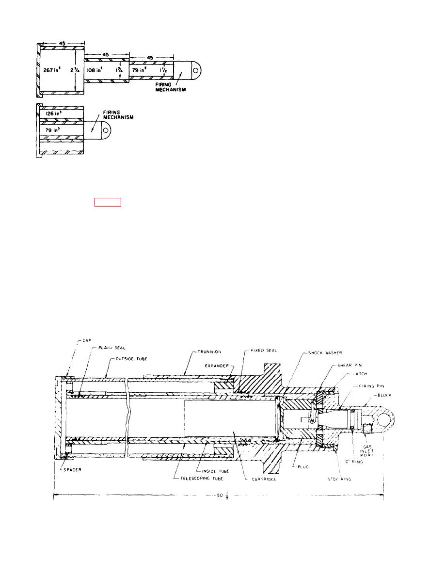
Figure 54. Expansion ratio with annular volume.
perforated H8 propellant will be used. (Approximately
20 percent has been added to the computed charge to
slow for experimental charge development.).
spacer; block; and cartridge. The design of these
components is described later in this chapter.
b. For convenience, it w-as decided to use single
perforated H8 propellant grains of 0.318 inch diameter.
These grains are 2.73 inches long and 0.2 cubic inch in
from an initiator.
Pressure behind the firing pin
volume, and 13 or 14 will fit in the cartridge. Since the
increases until it provides sufficient force to shear the
density of H8 propellant is 0.057 lb/in.3 (table XIII),
shear pin and drive the firing pin toward the primer. As
approximately 7.6 cubic inches or 35 propellant grains
the firing pin moves, the safety lock recesses in the
are required. A standard cartridge case (M36A1) is of
latches are cleared and the tapered sides of the firing
the required diameter and about 9 inches long, and can
pin center section cause the catapult latches to be
be used for the preliminary design.
drawn toward the center, unlocking the catapult. The
firing pin strikes the cartridge firing plug which, in turn,
strikes the primer and fires the cartridge.
g. Propellant gas, generated by the catapult
cartridge, causes the cartridge case to rupture,
permitting the propellant gas to flow into the inside tube
and through the spacer into the annular volume between
the outside and telescoping tubes. Pressure in the
Figure 55. Catapult component layout.
73


