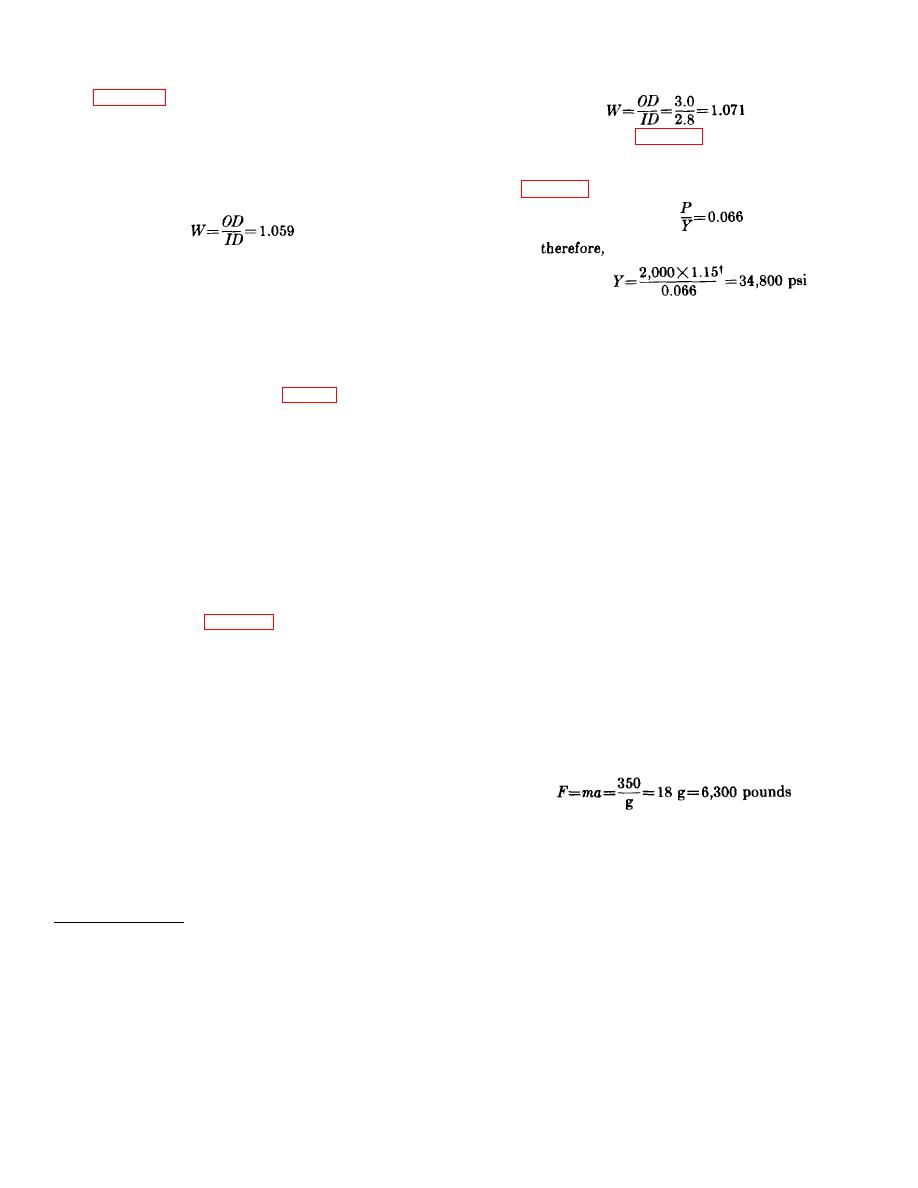
Using figure 23 and the ordinate of the intersection of
pressure ratio 0.055 and the biaxial stress curve
(catapults are subjected to radical and tangential
Referring to sheet 1 of figure 23, the pressure ratio (P/Y)
stresses but not to longitudinal stresses), the wall ratio is
is found to be 0.066 and the minimum strength of the
found to be 1.059. Since wall ratio is the ratio of outside
material is calculated as follows:
diameter to inside diameter, the outside diameter is
From figure 23:
calculated as follows:
therefore,
OD = W X ID = 1.059 X 1.50=1.59 inches
Since the yield strength of 2024-T3 aluminum is 42,000
This is the diameter of the base of the machined groove
psi, the material provides more than the required safety
and the relieved section, not the outside diameter of the
factor of 1.15 and can be used for the outside tube.
inside tube. Since the groove must be at least 1/16 inch
deep, the diameter of the inside tube must be 1/8 inch
64. Trunnion.
larger than 1.59, or 1.72 inches (fig. 57). Referring to
a. The trunnion (fig. 59) is a cylindrical alloy-steel
tubing standards, it is found that 1.740-.005 is a
body which has two pivots, 180apart, perpendicular to
standard size tube.
the longitudinal axis of the catapult. The trunnion has
f. It is assumed that the telescoping tube will also
internal threads to accommodate the stop ring which
be made of aluminum. The tube size is determined in a
serves as one bearing surface for the latches. The
manner similar to that used for the inside tube. The
recess in the trunnion below these threads serves as the
inside diameter of the telescoping tube is 1.75 inches
other bearing surface for the latches. The stop ring-
and the outside diameter is 2.00 inches. Again, the
trunnion combination, for positioning the latches, is used
large outside diameter is not calculated from the wall
in most catapults and removers because of its ease of
ratio, but rather the diameter of the undercut at the end
assembly. The upper portion of the trunnion's large
of the tube is found. Using the wall ratio already found
bore is threaded to accommodate the outside tube. The
(1.059), the minimum diameter of the -undercut is found
small bore of the trunnion acts as a bearing surface for
to be 1.86 inches. The telescoping tube of the final
the telescoping tube. A spring (tortuous path) seal is
design is illustrated in figure 58. From the figure it can
provided in the trunnion to seal the telescoping tube.
be seen that although the standard 2-inch tube is
b. The trunnion pivots are an integral part of the
machined down over most of its length, the last 3 inches
trunnion. The diameter of these pivots is computed on
(near the shoulder) are tapered and the final 1 1/4
the basis of shear strength. The maximum static load
inches of the tube are 2.00 inches in diameter. This
applied to the pivots, according to the design
increase in diameter of the telescoping tube is designed
requirements, is 6,000 pounds. The maximum kinetic
to create an interference fit (0.000 to 0.007 inch)
load applied to the pivots, resulting from operation of the
between the telescoping tube and the trunnion bore, and
catapults, is computed by using Newton's law:
thus absorb some of the energy of the moving members
before the telescoping tube and its attached spacer
strike the stopping shoulder of the trunnion.
g. In the estimate, the outside tube was calculated
to have a 3-inch outside diameter and a 2 3/4-inch
Since the kinetic load is greater than the static load
inside diameter. A commercially available tube made of
specified (6,000 pounds) in the design requirements, the
2024-T3 aluminum (WW-T-785) has an outside
kinetic load is used in calculating the size of the trunnion
diameter of 3.0 inches and an inside diameter of 2.8
inches. The wall ratio of this tube is:
† Safety factor.
77


