
TM 3-6665-329-13&P
3-25 DIAL INDICATING DIFFERENTIAL GAGE.
This task covers:
a.
Removal.
Installation.
b.
INITIAL SETUP
Tools:
Electronic equipment tool
kit TK-105/G
Materials/Parts: Three machine screws NSN 5305-00-054-6662.
Equipment Condition: Lid and panel assembly removed during troubleshooting.
Removal.
a.
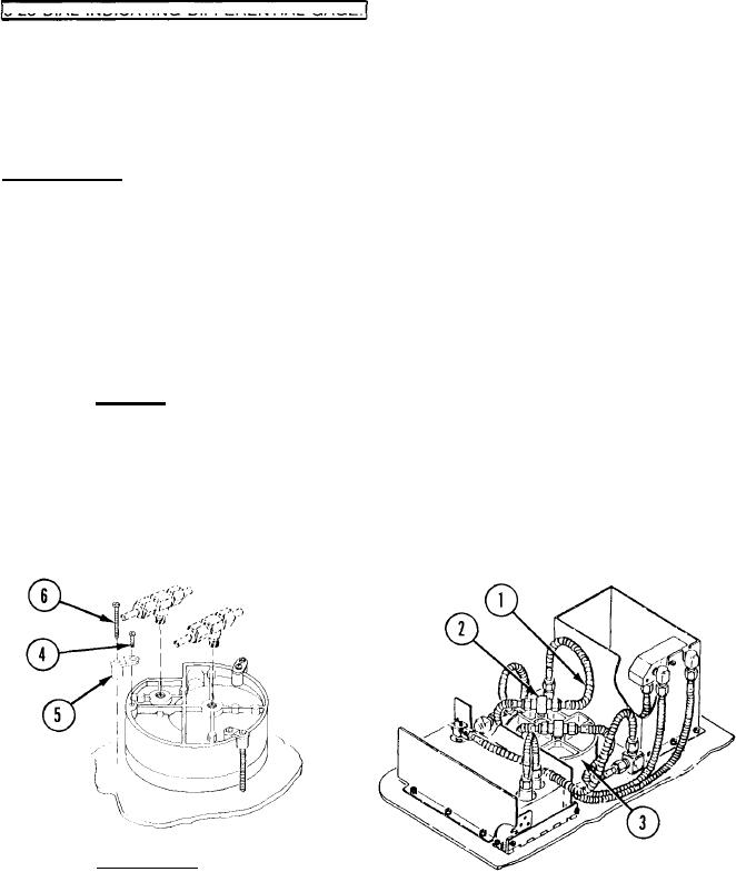
(1) Label and remove nonmetallic tubing (1) from two tee fittings (2).
(2) Remove two tee fittings (2) from PRESSURE-VACUUM GAGE (3).
(3) Remove three mounting screws (4) which secure three rim latches (5).
(4) Remove PRESSURE-VACUUM GAGE (3) through front of panel assembly.
Installation.
b.
(1) Remove three machine screws (4) and three lugs (5). Install screws (6) into lugs
approximately halfway.
(2) Install replacement PRESSURE-VACUUM GAGE (3) into front panel assembly.
(3) Secure gage with three lugs (5) and tighten three screws (4).
3-76