cartridge end has external threads to which the block is
c. A standard head is selected for the cartridge.
attached. The outside surface of the inside tube is
The top of the cartridge head has a shallow, lard
machined, except at the ends (fig. 57) to a slightly
diameter recess which is used to position the retaining
smaller diameter to reduce friction as it strokes. Four
ring, which retains the firing plug and M61 primer. The
slots are machined in the cartridge end of the inside
primer cavity is located in the bottom of the cartridge
tube to provide a means of locking the block to the tube.
head and has sufficient depth to hold the primer and
Three holes in the block provide a locking position (the
firing plug. The igniter is retained in an annular cavity
position where a slot in the tube and a hole in the block
having a semicircular cross section. The approximate
are aligned) every 30
.
igniter charge may be found using the method described
b. The telescoping tube is a long cylinder, the base
in chapter 4. Black powder is commonly used as an
igniter in propellant actuated devices Assuming that 40
of which has a larger outside diameter than the cartridge
grams of black powder are required for each pound of
end. The base is threaded to accommodate the internal
propellant, the igniter charge for the M3 catapult
threads of the spacer. (The functions of the spacer are
cartridge is:
described later in para. 69.) The outside diameter of the
telescoping tube is enlarged for the last 1 inch (at the
spacer end) to act as a stopping shoulder in arresting
0.408 lbρ x 40 gm/lbρ = 16 gm
the motion of the telescoping tube as it approaches the
stopping shoulder of the trunnion. Eight holes are
This charge, as well as the propellant charge, is subject
located around the circumference of the telescoping
to modification during the evaluation program. For
tube (fig. 58) to permit propellant gas to enter the space
example, the M36A1 cartridge uses 65 grains of igniter.
between the telescoping and inside tubes and equalize
d. A disc and retaining spring are provided at the
the pressures within all three tubes.
base of the head to separate the igniter from the
c. The outside tube is a long cylinder with external
propellant. The igniter is retained in the igniter chamber
threads at each end. The cap is used to close the
by a thin magnesium wafer (igniting charge disc) which
bottom end and the trunnion is attached to the top (the
ignites when the igniter burns. Four flash holes connect
cartridge end of the device).
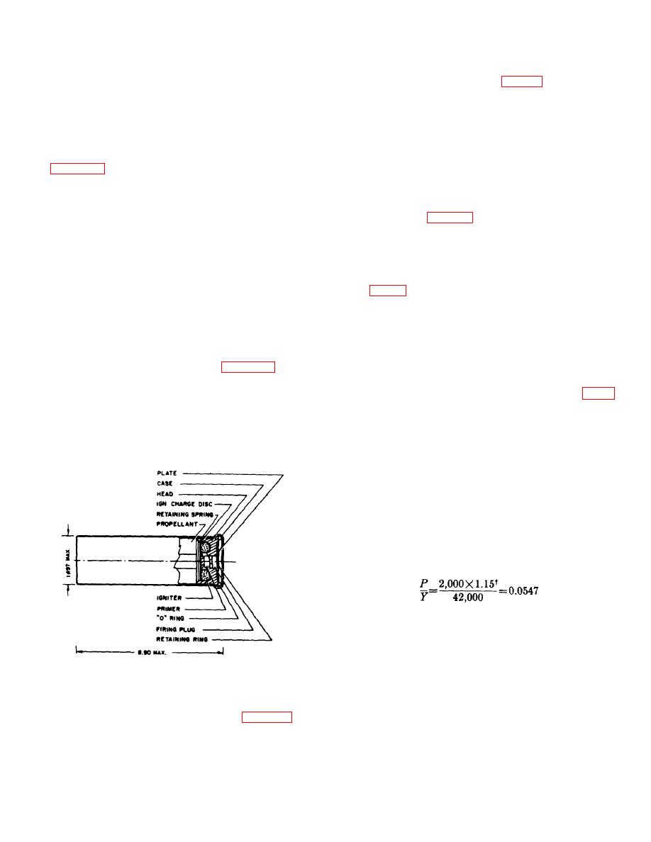
the primer and the igniter chambers. Figure 56 shows
the cartridge has been standardized as the M36.
d. The sizes of the tubes are calculated using the
equation of von Mises-Hencky, which is plotted in figure
63. Tubes. a. The tubes of the catapult act as both the
23. Catapults generally are not designed to withstand
pressure chamber and the stroking members. The
locked-shut pressures; therefore, the peak pressure
inside tube is a long cylinder with grooves on the outside
assumed in the first order approximations (2,000 psi)
of the tube at each end to accommodate wire (tortuous
may be used in the calculations.
path) seals. The
e. It was assumed previously that the inside tube
had a 1l/2-inch inside diameter and 1/8-inch walls (a
standard wall thickness in tubing of this size), while the
telescoping tube had a 13/4-inch inside diameter and
1/8-inch walls. These nominal sizes are used in the
following calculations. The outside diameter of the
inside tube must be large enough to permit grooves to
be machined in each end for insertion of the wire seal.
Assuming that aluminum will be used for the inside tube
to minimize weight, the pressure ratio (P/Y) is:
Figure 56. Catapult Cartridge, M36
† A 1.15 safety factor to used, since this it a cylindrical part which must withstand Internal pressure without rupturing (see
Design Strength considerations, section III, chapter 4).
74


