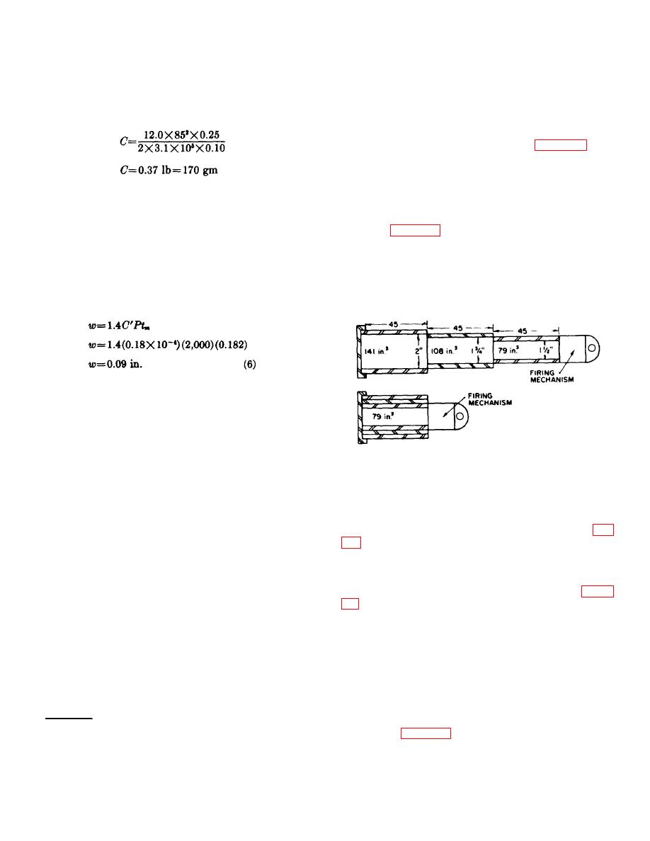
tubes are each 45 inches long, thus providing the
efficiency of 10 percent and also
necessary stroke.
assuming that H8 propellant will be used.
The value of propellant impetus, F, for H8
c. After the tubes are placed in the envelope
propellant is 3.1X105 ft lb/lb and γ is
(based on approximated lengths and diameters) and
approximately 1.25 for propellants used in
space is provided for the firing mechanism, the initial
propellant actuated devices.
and final volumes are calculated. It is desired to make
the ratio of final volume to initial volume (expansion
ratio) approximately 2. Assume, as in figure 53, that
each stroking tube is 45 inches long, that the inside
diameter of the inside tube is 1 1/2 inches (which may
be obtained by making the walls of the telescoping and
inside tubes 1/s inch thick), and that the telescoping and
e. Grain Geometry.
outside tubes fit over the inside tube without airspace.
(1) The grain used in this catapult should be
The expansion ratio calculated for the assumed device
cylindrical with a single perforation. †.
shown in figure 53 is slightly greater than 4, which is
The thickness of the web is estimated by
twice as large as that desired. To reduce the expansion
using equation (6). Peak pressure and
ratio and still maintain the required stroke, it is
stroke time have already been estimated,
necessary to increase the initial volume. Since the
and the pressure coefficient of linear
device cannot be lengthened (overall length is specified
burning rate (C') for H8 propellant, is
as 50 1/2 inches), the diameter of the device must be
given in table XIII.
increased.
(2) The web estimated above can be used in
the initial charge, but it may have to be
modified during the charge establishment
firings, since it is based on two other
approximations: peak pressure and stroke
Figure 53. Expansion ratio approximations.
time.
61. Component Layout. a. The component layout is
used to place sufficient stroking members within the
tubes are kept constant, but the outside tube diameter is
required envelope to give the required stroke, and to
increased to 3 inches and vented spacers are provided
estimate the cartridge size and internal volumes.
to permit propellant gas to flow into the annular volume
Ballistically, this requires the volumes at the beginning
between the outside tube and the telescoping tube (fig.
and end of stroke in order to complete the calculations.
b. The initial layout starts with the specified overall
approximately 200 cubic inches and the final volume to
approximately 450 cubic inches. The expansion ratio is
length (50 1/2 in.) and assumes the 2-inch outside
now approximately 2, and the design may be continued,
diameter for the telescoping tube previously estimated.
using the general layout of components shown in figure
The necessary components, such as the cartridge, firing
mechanism, and stroking members, are then fitted to
the layout. As previously determined, two moving tubes
e. The layout of the catapult includes the following
are required. (The envelope tube is generally referred
components: a cap; outside, telescoping, and inside
to as the outside tube; the innermost tube is called the
tubes; seals; trunnion; locking mechanism; firing
inside tube; and the intermediate tube between these
mechanism; shock washer; expander;
two is called the telescoping tube.) As a first
approximation, assume that the telescoping and inside
† The selection of propellant and propellant grain geometry are discussed In chapter 5.
72


