CHAPTER 4
DESIGN TECHNIQUES
Section I. INTRODUCTION
17. General. This chapter provides a basic knowledge
c. Method of initiation.
of the preliminary design of propellant actuated devices.
d. Minimum mounting strength (structural loads).
Methods of approximating parameters not generally
e. Open or closed type system.
given in design requirements are presented. Materials,
f. Initial and/or final lock requirements.
safety factors, and methods of calculating wall strengths
g. Propelled mass.
and selecting tube sizes to be used in propellant
h. Velocity.
actuated devices are discussed.
The design of
individual components of the devices is described, and
i. Maximum acceleration.
the use of protective finishes and dissimilar metals is
j. Maximum rate of change of acceleration.
outlined.
k. Ignition delay.
18. Design Requirements. The customary starting
l. Resisting or assisting forces.
point in the design of propellant actuated devices is the
m. Strokes (must be compatible with h, i, and j
requirements which list in detail the size, weight,
above).
strength, and performance of the device. A typical list
of design requirements includes the following.
n. Special requirements such as bypass and buffer
or damper requirements.
a. Maximum envelope dimensions.
b. Maximum weight.
Section II. METHOD OF FIRST ORDER APPROXIMATIONS
20. Stroke to Separation. a. The requirements for
19. General. Not all significant parameters are defined
catapults, removers, and occasionally thrusters specify
in design requirements. The design requirements may
specify acceleration, rate of change of acceleration, and
velocity, but, not the stroke necessary to satisfy these
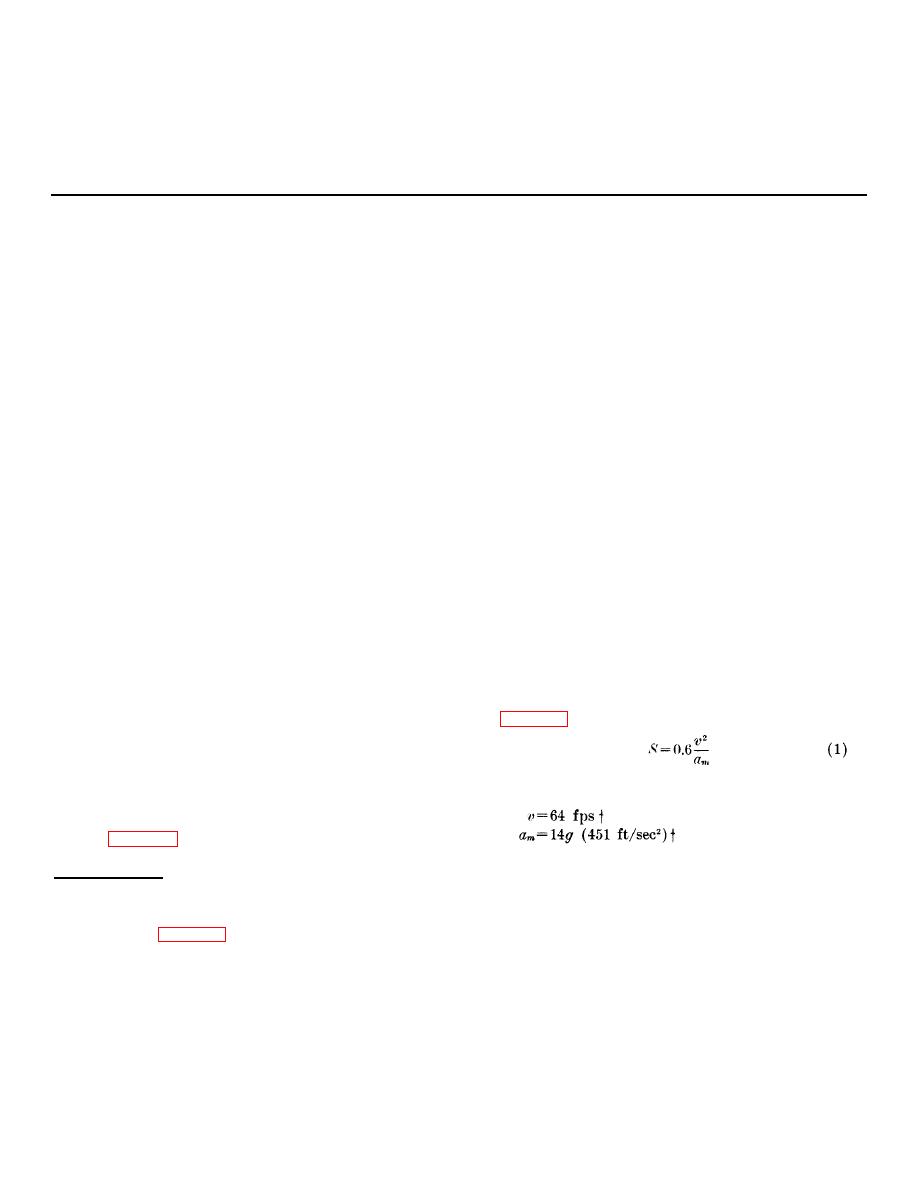
maximum rate of change of acceleration, a The
.
requirements. Stroke and velocity but not acceleration
stroke, S, of such devices can be estimated by using the
may be specified for thrusters.
The envelope
following equation, the derivation of which is contained
specifications may give exterior dimensions but not the
in chapter 5.
internal volume and expansion ratio nor the propellant
charge and cartridge size. The unspecified parameters
must be determined by the designer in conjunction with
b. The M5 catapult, for example, has the following
the ballistician. Methods of approximating stroke, stroke
performance characteristics when fired at 70 .:
F
time, working pressures, and propellant charges are
presented here. The last parameter is treated in greater
detail in chapter 5.
† The quantities used here are the actual quantities measured during the development of the M5 Catapult. They are used in
these equations to illustrate the usability of the equations. The acceleration and rate of change of acceleration are usually given as
specified maxima. The values of these two quantities to be used in these equations for preliminary design are chosen by the designer
from experience. Chapter 6 gives step-by-step use of the equations for some examples.
24


