
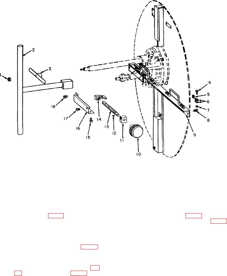
1
Nut
7
Nut
13
Adjusting screw
2
Old valve wrench
8
Screw
14
Adjusting key
3
New valve wrench
9
Key guide
15
Screw
4
Screw
10
Adjusting knob
16
Screw cover
5
Nut
11
Adjusting screw retainer
17
Screw
6
Key clamp
12
Pin
18
Screw
Figure 15. Shield adjustment assembly.
assembly, the inner socket (12, fig. 14) and outer socket
(c) Remove the nut (1, fig. 15), new valve
(24) are not replaceable. However, the three ball
wrench (3) and yoke collar (6, fig. 14)
screws (9, 11, and 22) and the two lug screws (10 and
from the new valve socket (14) and
23) are replaceable by organizational maintenance
remove the new valve socket wrench
personnel.
assembly.
(1) Removal.
(d) Remove four nuts (13) and screws ,which
(a) Turn the wrench holder (12, fig. 16)
hold the outer socket (24) to tile inner
socket (12).
clockwise to the old valve position and
(e) Loosen the three ball screws (9, 11, and
lock the lock bolt (10) before removing
the ball assembly.
22) and two lug screws (10 and 23) and
(b) Remove the old VaIve wrench (2, fig.
lift the outer socket (24) over the ball
assembly.
wrench shaft spring (8) from the old
Note
valve socket (16) and remove the old
Do not remove the ball screws or lug
valve socket wrench assembly.
screws unless they are damaged.
TAGO 5013-A 22