the hole at the end of the slot and in the
(f) Lift the ball assembly from the inner
end of the lock bolt. Place the lock bolt
socket.
so that the notch that engages the
(2) Disassembly.
plunger (8) is at the outer end of the
(a) Stand the ball (9, fig. 16) on a flat
wrench holder.
surface with the wrench holder plate (5)
(c) Slide the lock bolt (10) toward the center
uppermost and remove the lock bolt
of the wrench holder (12) and insert the
screw (2).
lock bolt end of the wrench holder into
(b) Remove the two plate screws (1) and
the spherical end of the ball (9). Push
carefully lift the wrench holder plate (5)
the wrench holder into the ball until the
off the ball (9).
lock bolt drops into the groove around
(c) Slide the lock bolt (10) out of the lock
the inside of the ball. Turn the wrench
bolt hole in the ball (9) and carefully lift
holder clockwise in the ball until the lock
the ball off the wrench holder (12).
bolt engages the lock bolt hole at the old
(d) Remove the lock bolt spring (11). The
valve position.
wrench holder is now free.
(d) Put the wrench holder plate (5) over the
(e) Remove the two screws (13) and ball lug
end of the ball and screw the lock bolt
(14) from the ball (9).
screw (2) through the slot in the wrench
(3) Assembly.
holder plate into the hole in the lock bolt
(a) Install the ball lug (14) on the ball and
(10). Unlock the lock bolt and secure the
secure with two screws (13).
wrench holder plate (5) to the wrench
(b) Insert the lock bolt (10) and lock bolt
holder (12) with the two plate screws (1).
spring (11) in the slot in the end of the
wrench holder (12). Seat the spring in
1
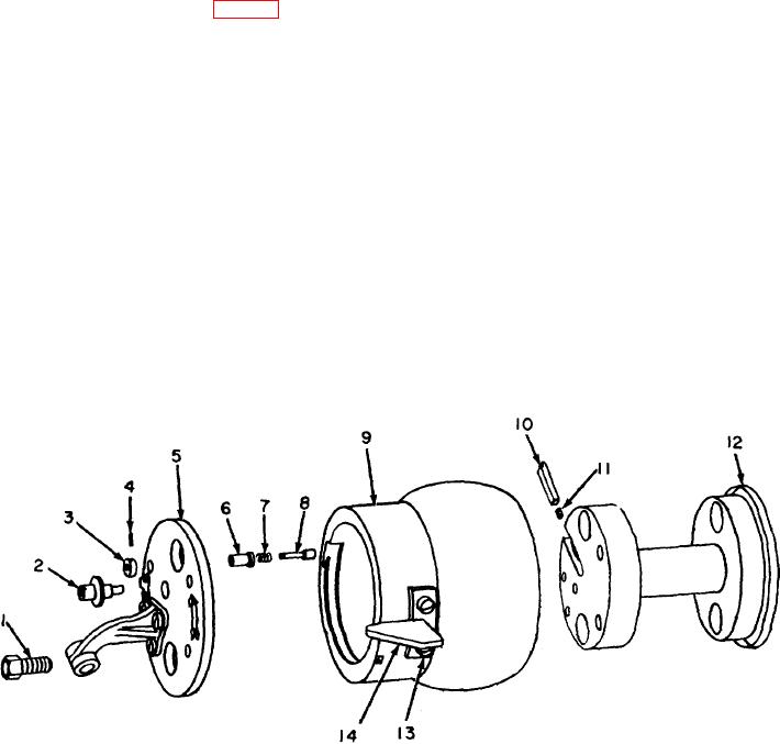
Plate screw
8
Plunger
2
Lock bolt screw
9
Ball
3
Plunger collar
10
Lock bolt
4
Pin
11
Lock bolt spring
5
Wrench holder plate
12
Wrench holder
6
Plunger housing
13
Screw
7
Plunger spring
14
Ball lug
Figure 16. Ball assembly.
TAGO 5013-A 23

