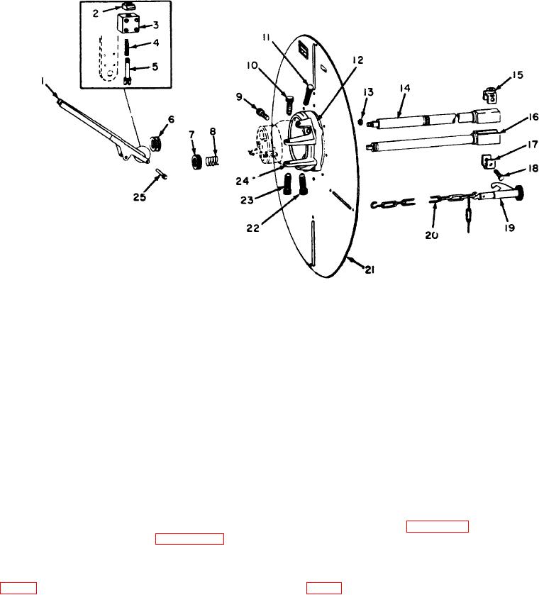
1
Valve socket lever
9
Ball screw
17
Socket cap
2
Lever lock knob
10
Lug screw
18
Socket cap screw
8
Lever lock body
11
Ball screw
19
Chain coupling assembly
4
Lever lock spring
12
Inner socket
20
Chain
5
Lever lock plunger
13
Nut
21
Shield
6
Yoke collar
14
New valve socket
22
Ball screw
7
Spring collar
15
Socket cap
28
Lug crew
8
Wrench shaft spring
16
Old valve socket
24
Outer socket
25 Valve socket lever pin
Figure 14. Lever, ball, socket, and shield assembly.
and lever lock body (3) and screw
the holes in the key clamps and adjusting key, secure
the plunger into the lever lock knob
each pair of key clamps to each adjusting key with two
(2).
screws (4) and nuts (7).
(c)
Install the lever lock pin (25).
29. Assembly
28. Shield Adjustment Assembly
a. Description. The description
of
the
ball
a. Description. The description of the shield
assembly is given in paragraph 9.
adjustment assembly is given in paragraph 11.
b. Maintenance. Organizational maintenance
b. Maintenance. Organizational maintenance
personnel are authorized to replace certain parts of the
ball assembly. These parts include the plate screws (1,
personnel are authorized to replace the key clamps (6,
fig. 16), lock bolt (10), lock bolt spring (11), and ball lug
fig. 15) on the shield adjustment assembly.
(14). The other components are either not stocked, or
are authorized for replacement by direct support
(1) Removal. Remove the two key clamps (6)
maintenance personnel. In removing the ball
from each of the four adjusting keys (14) by removing
two nuts (7) and screws (4) from each set of key clamps.
(2) Installation. Place a key clamp (6) on each
side of the leg of the adjusting key (14) and after alining
TAGO 5013-A 21

