retracting type thrusters (where the piston
withdraws into the device) as well as the
pushing type thruster. In either case,
mechanical stops prevent the ' cylinder
piston from returning to its initial position
after the thruster completes its stroke.
This method prevents damage not only to
the device being tested but protects the
instrumentation as well.
(4)
As mentioned briefly in paragraph 93d,
the strain-resistant type of load cells
shown are subject to damage and
nonlinearity when used for extremely fast
rise time measurements. To overcome
this problem, a hydraulic load cell was
developed. This device, not illustrated, is
made from a hydraulic jack which is
modified by adding a pressure tap to the
fluid chamber.
The fluid pressure is
measured by a pressure transducer.
(5)
The stroke marker indicated in figure 100
is a lucite rod wound with nichrome wire.
A voltage is impressed across this wire.
The pitch of the windings is 0.1 inch. The
wiper, driven by the thruster piston,
contacts each turn of the wire as it moves
forward, producing a series of electrical
impulses for display on recorder.
(6)
A rectilinear potentiometer can also be
used in the conventional way to provide a
stroke-time record. However, the high
accelerations and vibrations of thrusters
during the stroke often damage the
potentiometer.
Therefore, in spite of
problems of wiper skip, the lucite rod
stroke marker has proved more useful.
(7)
The electrolytic bath type stroke marker,
described
in
instrumentation tion, may also be used.
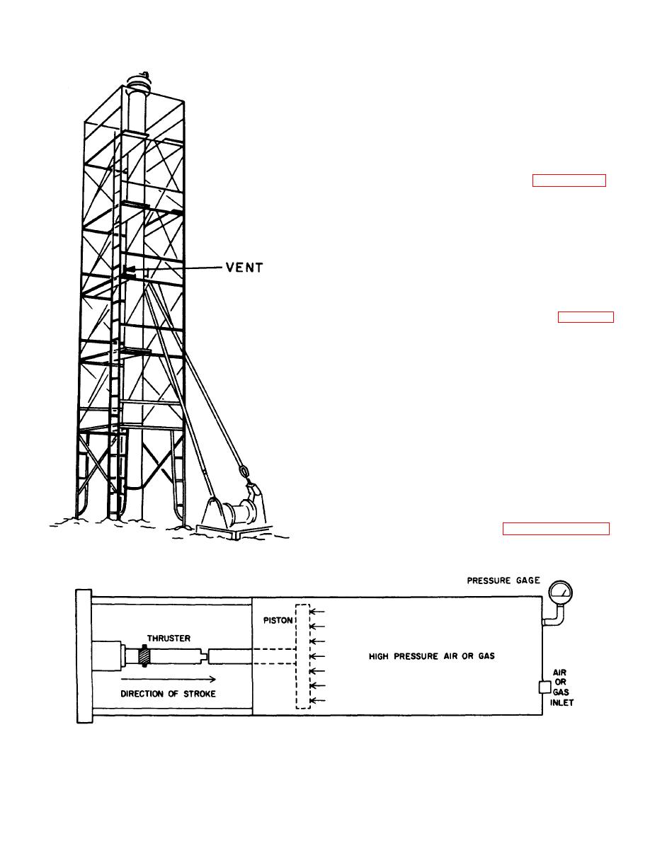
Figure 97. Another type of vertical test tower.
Figure 98. Pressure cylinder.
108


