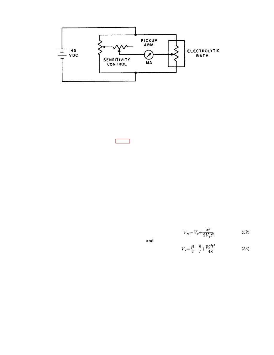
Figure 92. Schematic diagram of linear electrolytic positioning transducer.
of the original techniques are presented to
carbon rods at specific intervals (arranged
suggest the many ways in which velocity
so they will be broken by transit of the
may be measured.
carriage) and using these carbon rods as
part of a "make" or "break" circuit to start
(2) The velocity of a catapult load in free
and
stop
counter
chronographs.
flight has been measured by measuring
Photoelectric cells have also been used in
the time of flight from the moment of
conjunction with counter chronographs.
separation, when the catapult inner tube
and the ejected mass move upward until
(6) A recently developed linear electrolytic
the ejected mass falls to a horizontal
positioning transducer is shown in figure
plane a few feet above a recovery pit. To
92.
This transducer consists of an
use this technique, the catapult is
insulated container filled with an
mounted a few degrees from the vertical
electrolyte. One end of a pickup (wiper)
and oriented with respect to the recovery
arm is rigidly connected to the stroking
pit. A light beam is directed across the
member of the propellant actuated
trajectory of the weight to a photoelectric
device, and the other end is suspended in
cell so that the beam is interrupted by the
the electrolytic solution. The transducer is
weight at a time corresponding to tube
connected to a helipot, to form a
separation.
This interruption starts a
Wheatstone bridge, with the pickup arm
counter chronograph. As the descending
acting as the balance (galvanometer)
weight passes through a plane of light
arm. The helipot. is used to balance the
slightly above the ground level, an
bridge. As the pickup arm moves, it
amplifier is triggered causing the counter
unbalances the bridge. This unbalance is
chronograph to stop. The velocity of the
directly proportional to the movement of
catapult at separation may then l)e
the arm, thus it is directly proportional to
computed using the following equation:
the stroke.
A microammeter in the
balance arm indicates the amount of
bridge unbalance.
The transducer is
calibrated by simulating various amounts
of wiper arm displacement and recording
t-he meter readings at these points.
g. Velocity Measurements.
Where:
(1) Several methods of measuring velocity
have been described above.
These
Vm = velocity at separation
methods included integrating acceleration
x = horizontal distance of flight
time
curves
and
using
counter
t = time of flight
chronographs, magnetic pickups, or other
g = acceleration due to gravity
stroke-time markers.
Although the
h = difference in height between the begin-
methods already described are the most
ning and end of trajectory
commonly used at the present time, a few
p = air drag force divided by ejected mass
and velocity squared
103


