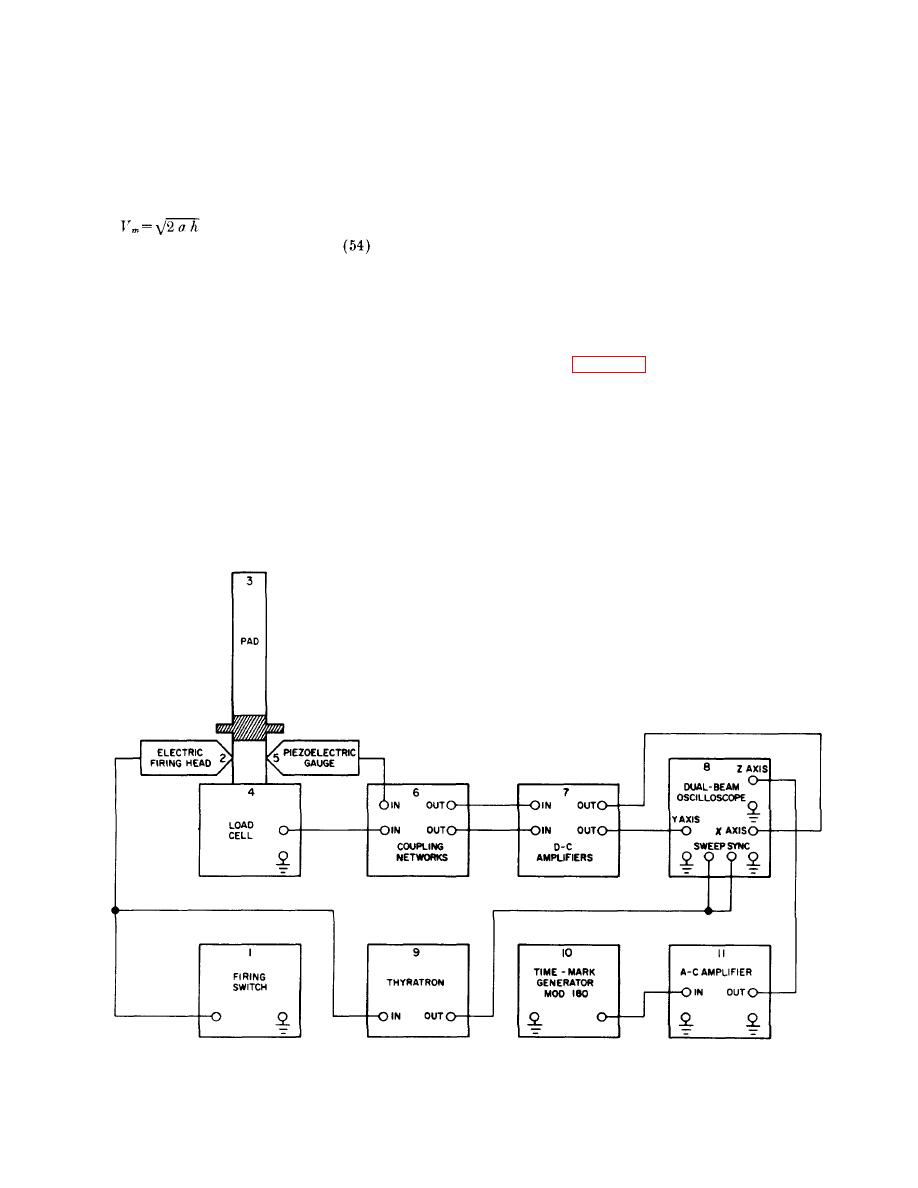
The signals generated by the load cell and
(3) Another indirect method of measuring the
piezoelectric gage are passed through
velocity of catapults, which is useful when
coupling networks (6), amplified (7), and
the propelled weight is fully guided, is to
fed into a dual-beam oscilloscope (8).
calculate the separation velocity on the
basis of the height of travel. This may be
(2) The firing switch (1) not only fires the
calculated from the following formula if
device, but supplies current to fire a
the height of travel of the ejected mass, h,
thyratron (9), which triggers the scope,
and the acceleration, a, are known:
and therefore, synchronizes the sweep of
the scope with the firing of the propellant
actuated device. One-half millisecond
time dots are generated by a time-mark
The velocity determined in this manner is
generator (10), and after amplification
slightly lower than the actual velocity,
(11), they are fed into the oscilloscope (8)
unless a correction for friction is applied.
in the form of Z axis modulation of the
h. Typical Instrumentation Setup.
trace. They appear as dashes along the
trace.
(1) A typical instrumentation setup permitting
cross-checking of test results is presented
(3) Figure 94 shows a typical record obtained
in figure 93. When the firing switch (1) is
with the instrumentation described above.
thrown, current flows to the electric firing
The sweep speeds of the oscilloscope
head (2), which fires the propellant
were adjusted to separate the curves for
actuated device (3). When the device is
easier reading.
With most propellant
fired, the reactive thrust is measured by
actuated devices (particularly catapults),
the load cell (4), and the internal pressure
additional transducers are used and all
of the device is measured by the
curves are shown on a common time
piezoelectric
gage
(5).
base by using a multichannel oscillograph
as the recorder.
Figure 98. Complete test instrumentation block diagram.
104


