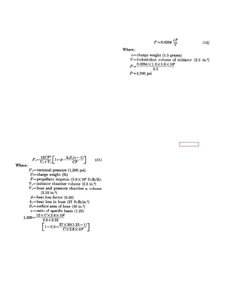
1,500 = 9.0 X 10⁵C(0.7 - 56 X 10-5C-1) C = 3.2 X 10⁻³
Lanyard travel .....................3/4-inch.
Generated pressure.............1,500 psi in a 1.00 in.3
pounds = 1.5 grams
chamber at end of a
e. With this calculated charge, the locked-shut
4-foot hose.
pressure may be estimated with equation (13).
Ignition delay ......................2 seconds.
84. First Order Approximations . a. The propellant
charge must be calculated prior to estimating the peak
pressure which the device must be designed to
withstand. The propellant charge can be calculated on
the basis of the pressure which is to be generated in the
pressure gage chamber and the volumes of the pressure
chamber, hose, and initiator chamber.
b. The volume of the pressure gage chamber is
f. The device, therefore, should be designed to
specified as 1.00 cubic inch. The volume of the hose
withstand a maximum locked-shut pressure of 5,700
can be calculated by multiplying the cross-sectional area
psi.‡ The approximations from which the charge is
(0.0276 sq in.) by the length of the hose in inches, and
calculated must be accurate enough so that a total
the volume of the initiator can be estimated from the
redesign of the components will not be necessary when
envelope dimensions.
the actual locked-shut pressure is determined.
c. The initial volume of the chamber (2.5 cu in.) is
computed from its dimensions, taking into account the
85. Component Layout. a. A rough estimate of
firing pin, housing, and cartridge retainer.
When
envelope size has been obtained during the first-order
calculating initial volumes, the case volume is included
approximations. The firing mechanism and cartridge
in the initial volumes, since the instant the cartridge
are designed to fit into the estimated envelope. The
fires, the cartridge case opens and it becomes part of
mounting flange, chamber, cap, firing pin, firing pin
the internal volume.).
housing, cartridge, cartridge retainer, initiator pin,
d. The computed volumes and equation (51) are
initiator spring, and firing pin release balls are designed
used to determine the propellant charge. Since it
in conjunction with the estimated envelope and firing
generally is desirable to burn the propellant as rapidly as
mechanism and cartridge designs. Figure 76 shows the
possible, a fast-burning propellant, such as M2, is
layout of components of the initiator.
selected. The charge weight is computed as follows:
b. The initiator is operated mechanically by
exerting a 20- to 35-pound pull on the initiator pin.
The firing pin is locked to the initiator pin by 3 balls.
Withdrawing the initiator pin retracts the firing pin,
compressing the initiator spring. When the firing-pin-
release balls pass from the smaller to the larger
diameter bore in the firing-pin housing, the balls leave
the initiator pin locking groove, permitting the initiator
pin and firing pin to separate and the compressed
initiator spring to drive the firing pin toward the primer.
The firing-pin-release balls are returned to their original
position in the recess as the firing pin moves into the
smaller diameter bore. As the firing pin completes its
travel, the firing pin tip passes through the small hole in
the forward end of the firing pin housing, striking the
cartridge. The motion of the firing pin is arrested by the
† A factor of 12 is introduced to permit Pt to be expressed in psi.
‡ A workhorse model is fabricated to withstand a pressure far in excess of 6,000 psi and charge-verification firings
are conducted. The calculated charge, 1.5 grams of M2 propellant, is the first charge used In the workhorse model.
After the charge has been modified to meet the design requirements, locked-shut firings determine the actual pressure
which the initiator must withstand.
91


