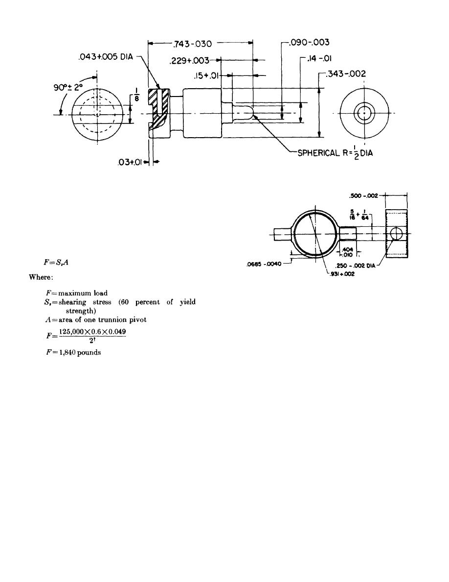
Figure 74. Thruster firing pin.
shearing stresses. Stress concentrations around the
trunnion pivots should be minimized by avoiding sharp
corners where the pivots join the trunnion ring.
c. The trunnion pivots must be strong enough to
permit the full tension load to be applied to the thruster
without deforming or shearing the pivots.
The
maximum load which the 0250-inch-diameter pivots can
withstand is -
Figure 75. Trunnion for thruster.
From this calculation, it is obvious that one pivot can
withstand the maximum load in shear. The trunnion
could also fail by tearing through the ring on both sides
of a pivot. The area which is subject to tearing is:
A =2 X trunnion ring thickness X trunnion width
A-=2 X 0.060 X 0.500
2
A= 0.600 in.
Section IV. M4 INITIATOR
Operating tempera ..............-65to 160F.
82. General. The M4 initiator (Delay-Initiator with
ture range.
Cartridge, Lap Belt Release, M4) was designed to
Envelope:
operate a lap-belt release or other propellant actuated
Maximum
device. The initiator is operated mechanically and
length ...........................6 inches.
contains a 2-second delay element.
Maximum width ................3 inches.
Maximum thick-
83. Design Requirements. The specifications for the
ness .............................2 inches.
M4 initiator include the following performance
Method of operation ............Mechanical, with 20-
requirements and physical characteristics:
to 35-pound pinpull.
† Safety factor of 2 is used for structural member.
90


