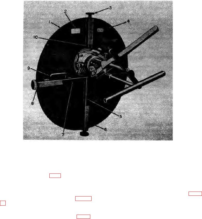
1
Shield
6
Screw cover
2
Nameplate
7
Center key guide
3
Adjusting knob
8
Adjusting knob
4
Marker plate
9
Handle
5
Lower key guide
10
Upper key guide
Figure 7. Shield assembly.
c. Handles. Two handles (9, fig. 7), bolted to the
The coupling hook hooks to a link of one of the coupling
chains. The coupling knob regulates the position of the
center key guide (7), provide grips for moving the shield.
coupling hook. Turning the coupling knob moves the
coupling hook into or out of the coupling body (1).
12. Adjustable Chain Coupling Assembly
b Coupling Chains. The coupling chains (4, fig. 11)
are seven-foot long steel chains, each with a chain hook
The adjustable chain coupling assembly (figs. 10
(1) at one end. A chain hook hooks into each hole in the
and 11) consists of two adjustable chain couplings and
end of the center key guide (2). The ends of the
two coupling chains.
coupling chains opposite from the chain hooks are
a. Adjustable Chain Couplings. Each adjustable
engaged by the coupling hooks on the adjustable chain
chain coupling consists of a coupling body (1, fig. 10),
coupling hook (3), and coupling knob (4). The coupling
body hooks over the rear rim of a one-ton container.
TAGO 5013-A 10

