position. When the wrench holder is swung
from the old valve position to the new valve
position,
the
lock
bolt
plunger
is
automatically raised by a shoulder in the ball
causing the lock bolt to be ready to lock in
the new valve position.
10. Valve Socket Lever Assembly
The valve socket lever assembly (fig. 6) consists of
a valve socket lever (4), a lever pin (1), and a lever lock
(6). A yoke (3) welded to the valve socket lever holds
two 3/8-inch steel pins (2) which engage the groove in
the yoke collar. Two holes in the end of the valve
socket lever receive the lever pin (1) when assembling
the
1
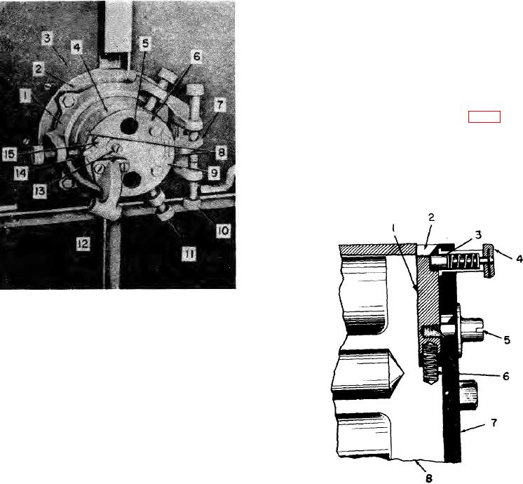
Outer socket
8 Lock bolt hole
2
Inner socket
9 Ball pointer
8
Shield
10 Lug screw
4
Ball
11 Ball screw
5
Wrench holder
12 Lever bracket
6
Wrench holder plate 13 Lock bolt screw
7
Ball lug
14 Wrench plate lug
15 Plunger collar
Figure 4. Ball and socket assembly.
(1), a lock bolt screw (5), a plunger (3), a
plunger collar (4), and a spring (6). It locks
the wrench holder (8) to the ball in the new
valve position or the old valve position. The
lock bolt screw (5) and plunger collar (4),
which are controls for the lock bolt (1) are
located on the wrench holder plate (7). The
1
Lock bolt
lock bolt (1), is located in a slot in the top of
2
Lock bolt hole
the wrench holder. The outer end of the lock
3
Plunger
bolt rides in the slot in the cylindrical
4
Plunger collar
projection of the ball and locks the wrench
5
Lock bolt screw
holder to the ball when it is forced by the
6
Spring
spring (6) into one of the two lock bolt holes.
7
Wrench holder plate
Lifting the plunger collar (4) raises the
8
Wrench holder
plunger (3) and allows the spring (6) to force
the lock bolt (1) outward into the locked
Figure 5. Lock bolt assembly.
position. Moving the lock bolt screw (5)
toward the center of the wrench holder plate
(7) returns the lock bolt (1) to the unlocked
TAGO 5013-A 8

