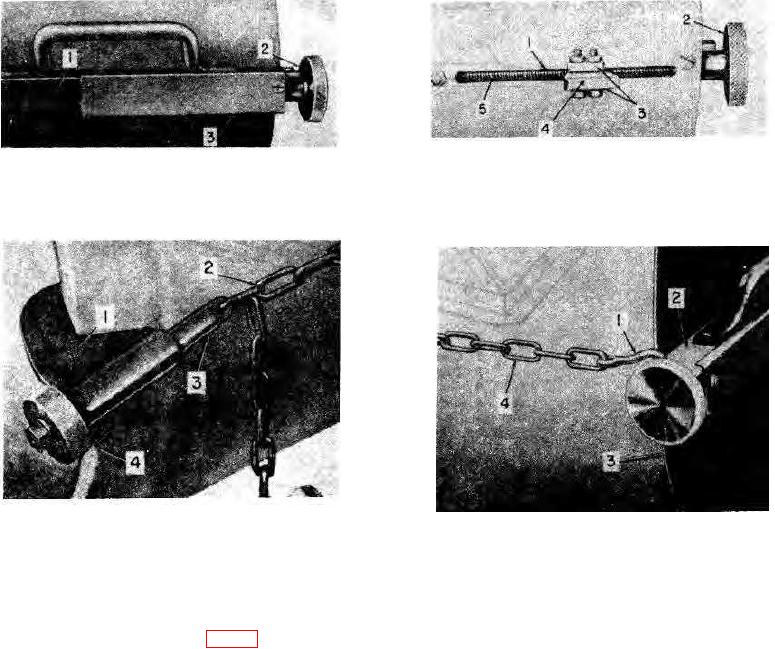
1 Slot
3 Key clamps
1 Key guide
2 Adjusting knob
2 Adjusting knob
4 Adjusting key
3 Screw cover
5 Adjusting screw
Figure 8. Shield adjusting mechanism, outer side.
Figure 9. Shield mechanism, inner side.
1 Coupling body
3
Coupling hook
2 Coupling chain
4
Coupling knob
1 Chain hook
3 Shield
2 Center key guide
4 Coupling chain
Figure 10. Adjustable chain coupling assembly,
rear end.
Figure 11. Adjustable chain coupling assembly,
front end.
13. Container Gage Assembly
The container gage assembly (fig. 12) consists of a
block (4) is welded to the intersection of the diagonals. A
container gage (3), a depth rod (2), and a clearance rod
hole drilled in one of the diagonals is used for bolting the
(1). The container gage and depth rod are used together
depth rod (2) and the clearance rod (1) to the container
to gage the depth of the eduction tube outlet below the
gage for storage and shipment.
rim of the one-ton container. The clearance rod is used
to gage the clearance between the valve being replaced
b. Depth Rod. The depth rod (2) is a steel rod 1
and the shipping bonnet nearest to it.
inches wide by 12-inches long by 3/8-inch thick. One
a. Container Gage. The container gage is made of
end is rounded and drilled to permit easy handling; the
11/2- by 1/8-inch structural steel angles welded together
other end is square. A beveled notch in one edge near
to form a 27-inch square with opposite corners joined by
the rounded end is marked MAX at one end and MIN at
diagonals. A sight
the other.
c. Clearance Rod. The clearance rod (1) is a flat
steel bar, 3 15/16 inches long, concave at one end and
convex at the other.
TAGO 5013-A 11

