
TM 3-4230-209-30&P
2-64
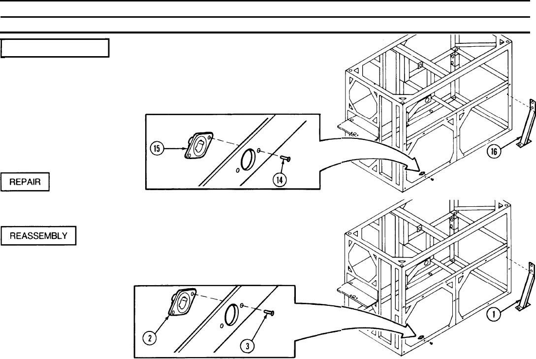
2-19. FRAME ASSEMBLY (CONT).
REMARKS
ACTION
LOCATION/lTEM
DISASSEMBLY (CONT)
Frame Assembly/
Chisel two blind rivets (14) out of each of the 26 turnlock receptacles (15)
Blind rivets (14)
as necessary. Do not remove turnlock receptacles (15) unless defective.
Turnlock receptacles (15)
Remove the two support angles (16) if installed
Support angles (16)
Replace all authorized components. Repaint frame assembly with
Frame Assembly/
polyurethane coating and a paint brush as necessary.
Position support angles (1) onto frame and aline holes.
Frame Assembly/
Position 26 turnlock receptacles (2) into frame and
Support angles (1)
aline holes. Secure each turnlock receptacle (2) with
Turnlock receptacles (2)
two blind rivets (3).
Blind rivets (3)