TM 10-5410-228-24
2.13.23 Cover Assembly Repair Continued.
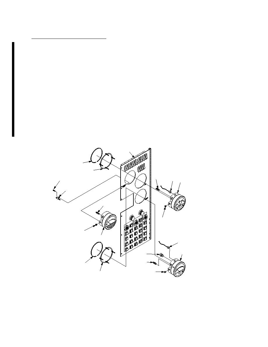
(31) Install vent filter plug (14) into HI port on back of gage PG1 (9).
(32) Install two plugs (12) on side of gage PG1 (9).
(33) Install gage PG1 (9) on front of cover (5).
NOTE
Spacer ring and retaining ring supplied with gage.
(34) From back of cover (5) secure gage PG1 (9) and spacer ring (11) to cover (5) with retaining ring
(10).
(35) Install connector (8) on back of gage PG1 (9).
(36) Install two barbed connectors (7) on back of gage PG2 (2).
(37) Install two plugs (6) on side of gage PG2 (2).
(38) Install gage PG2 (2) on front of cover (5).
NOTE
Spacer ring and retaining ring supplied with gage.
(39) From back of cover (5) secure gage PG2 (2) and spacer ring (4) to cover (5) with retaining ring
(3).
(40) Install connector (1) on back of gage PG2 (2).
5
3
4
7
1
15
2 (PG2)
16
19
6
18
17 (PG3)
8
9 (PG1)
14
13
10
12
11
(RACK AND PAN ASSEMBLY REMOVED FOR CLARITY)
109-1-M
Change 1


