TM 10-5410-228-24
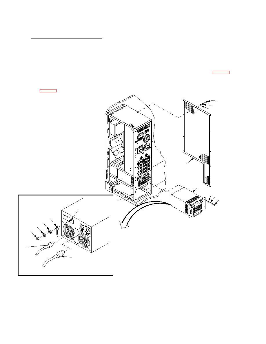
2.13.21 Inverter Replacement Continued.
(5)
Connect 1A4W12 cable assembly connector P2 (11) to inverter connector J2, located on the back
of the unit.
(6)
Push inverter (9) back into rack, ensuring the alignment post on the rear of the unit is seating
properly.
(7)
Secure inverter (9) to rack (5) with four screws (6), four new lockwashers (7) (Item 17, Appx E)
and four flat washers (8).
(8)
Secure guard (4) to side of rack (5) with eleven screws (1), eleven new lockwashers (2) (Item 17,
1
2
3
4
9
8
7
6
5
16
15
14
13
12
11
10
57-1-M
(ROTATED 90)
Figure 2-42. Inverter Replacement
Follow-on maintenance: Connect ECV battery ground cable per TM 9-2320-387-24-1, apply power and
perform operational test.
2-214


