T.O. 33B-1-1
1-64
1.8.2.5.2 Straight Beam Distance Calibration (Miniature Angle Beam Block).
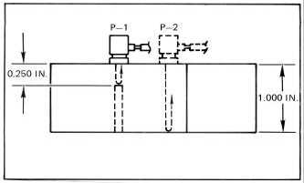
a. Position the search unit on the miniature block at P-1 or P-2 as shown in. The distance between
multiple back reflections is as follows: (see Figure 1-16)
b. Set the time base for the applicable distance calibration.
(1)
0.250 inch
at P-1
(2)
1.000 inch
at P-2
Figure 1-16. Straight Beam Distance with Miniature Angle Beam Block.
1.8.2.5.3
Straight Beam Distance Calibration (ASTM Blocks).
Distance calibration may be performed using multiple reflections from the FBHs or the back surfaces of ASTM blocks.
The procedures are identical to the procedures outlined above using the IIW block and the miniature angle beam block.
1.8.2.6
Calibration of Angle Beam Transducers.
NOTE
Do to a problem with the IIW Type 1 and Type 2 aluminum reference blocks, they
SHALL NOT be used for determining the point-of-incidence on shear wave search
unit having a refracted angle greater than 45° (i.e., 60°, 70°, etc.) Use a steel IIW
block instead.
1.8.2.6.1
Angle Beam Point Of Incidence (IIW Block).
The point-of-incidence is defined as the center point of the sound beam exiting the search unit wedge. It is usually
indicated by a mark on the side of the wedge at the point where an imaginary line through the exit point of the beam
intersects the side of the wedge.
a. Move the search unit back and forth from the curved surface at R-4 (see Figure 1-17) until the peak
signal from R-4 is obtained.
b. The search unit point-of-incidence now coincides with the line marked "0" on the block. Mark the
point-of-incidence on the side of the search unit.


