32. Length of Thread Engagement. After calculating
the tubing size necessary to withstand the stresses
be used to determine the maximum permissible
involved, the second most important calculations are
pressure when the tube size is specified. For example,
those for determining the length of engagement of
the maximum pressure permissible with a tube whose
threads. Threads are designed in accordance with
dimensions are 1.500 outside diameter and 1.248 inside
Bureau of Standards specifications. The length of these
diameter may be found as follows:
threads may be calculated by using equation (11). (The
derivation of equation (11) is given in appendix III.)
Assuming that there are triaxial stresses, P/Y=0.170 is
obtained from the tables in appendix II. If the material is
Where:
steel with a value of Y=125,000 psi, then P=0.1770 X
L=length of engagement of threads
125,000 =21,250 psi.
P=maximum internal pressure
e. Conversely, the maximum pressure could have
S3=shear strength
been estimated and the wall ratio taken from the table of
R=major radius of female (max)
d=minor diameter of male (min)
the envelope drawing, the necessary ID can be
This equation includes a 1.5 safety factor to allow for
calculated. The tubing size specified in the military
tolerances and the distribution of stresses within the
standards most closely approximating these dimensions
engagement.
would be used.
Section IV. DESIGN PROCEDURES
33. General. a. Typical procedures are presented here
which, with some variations, are used in the design of
propellant actuated devices. The procedures have
arbitrarily been divided into three categories: gas-
generating devices, stroking devices, and (multi-device)
systems. The design of special purpose devices (such
as cable cutters and gas operated trigger mechanisms)
is similar to that of gas-generating and stroking devices,
so it was not considered necessary to discuss these
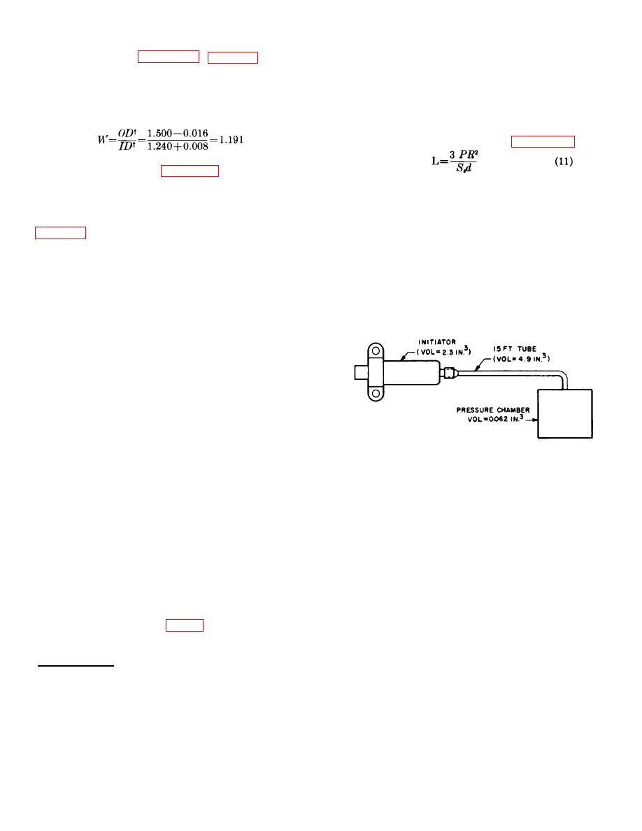
Figure 24. Simple PAD system using an initiator.
separately.
b. The discussion of systems, unlike those for the
b. The ballistician uses these three values to
gas-generating and stroking devices, does not present
estimate the propellant charge necessary to produce the
design procedures, but rather presents material on how
required pressure. The method of estimating this
systems are established and their reliability maintained.
pressure is described in the ballistics design discussion
34.
Gas-Generating Devices.
a.
The design
(chap. 5). The designer then calculates the maximum
requirements for gas-generating devices specify the
pressure which may be developed in the initiator when
pressure that is to be generated and where it is to be
the device is fired "locked shut." (The chamber is closed
measured. For example, an initiator may be required to
so that the internal volume of the chamber must contain
produce a pressure of 500 psi in an 0.062-cubic-inch
all of the gas generated by the burning propellant.) The
chamber at the end of a 15-foot tube. Using the
strength of the walls is calculated from the "locked shut"
envelope specified, the designer estimates the internal
pressure, using the curves or tables described
volume of the initiator, the volume of the tubing to be
previously.
used, and the volume of the chamber in which the
c. To estimate the locked-shut pressure, the "gas
pressure is to be measured (fig. 24).
law" is approximated as shown below:
† The smallest possible OD and largest possible ID are used. The numbers 0.016 and 0.008 are tolerances.
32


