they contain iron sulphide "stringers" or microstructural
31. Distortion-Energy Theory. a. The distortion-
sulphide inclusions, oriented in the direction of working,
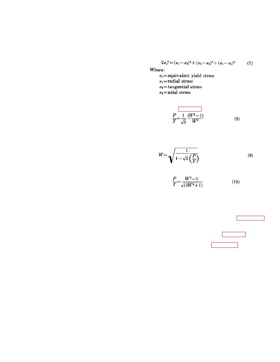
energy theory of failure (von Mises-Hencky) is the
and normal to the most critical stress, and thus are
accepted criterion for the design of ductile materials
inadequate in devices with high internal pressures.
under combined loads.
This theory defines an
28. Safety Factors. a. Safety factors used in the
equivalent stress that exists for a combined loading.
The distortion-energy equation for triaxial stresses given
design of propellant actuated devices may appear low,
in equation (7),
but they are adequate because they are subjected only
to controlled loads.
b. Safety factor of a part is established as a ratio
of the limiting stress to the design stress. All conditions
having an effect on the stress is included in the
determination.
c. Limiting stresses of pressure containing
structures is based on the minimum yield strength of the
is shown in more useful forms in equations (8) and (9).
material, and the design stress is based on the
The conversion of equation (7) to the forms of (8) and
Distortion Energy Theory in accordance with the von
(9) is shown in appendix I.
Mises-Hencky Concept.
Utilizing this theory, the
minimum factor of safety of the cylindrical section or
wall of the pressure chamber is 1.15.
d. The limiting stress of all other components also
Where:
corresponds to the minimum yield strength, but a
P=maximum pressure
minimum factor of safety of 1.5 is applied. In the cases
Y=yield strength of material
where shock or impact loads are applied, the minimum
W=wall ratio
factor of safety is 2.0.
29. Temperature Effects. Temperature has a marked
effect on the mechanical properties of metals at high
temperatures. The burning of propellant in the device is
When a device is designed to withstand only biaxial
for so short a time that the metal parts are unable to
stresses, equation (10) may be used.
absorb much heat; consequently, a negligible
temperature increase is experienced.
In addition,
propellant actuated devices are not exposed to ambient
temperatures exceeding 200 F., and the change in
b. The convenience of these forms of the
strength at 200F. is small and may be neglected.
distortion-energy equation is apparent when it is realized
30. Stresses. When calculating the sizes of metal
that the internal pressure, P, can be estimated and the
parts to withstand the internal pressures of propellant
strength of the material, Y, may be found in most
actuated devices, it is necessary to consider the
engineering handbooks. The wall ratio (ratio of OD to
stresses at the weakest part of the tubes, commonly at
the undercut at the end of the threads. The gas
contains a table of wall ratios for values of P/Y from
pressure inside the device produces a direct radial
0.010 to 0.200. This table was calculated from the
compressive stress which is greatest on the inside wall,
formulas presented in this section. Figure 23 presents
and induces a tangential stress (hoop stress) which is
curves of P/Y as a function of W for biaxial and triaxial
greatest also at the inside wall. In undamped stroking
stresses, based on the tables of appendix II.
devices, the stresses are biaxial (radial and tangential),
c. The wall ratio, W, may be used to determine the
but occasionally a longitudinal stress is introduced in the
tube size. Tubing is supplied in standard sizes and it
tube due to axial loading and the stresses become
may be necessary to use a tube which is stronger than
triaxial. Biaxial stresses put greater strains on materials
required (higher W) to avoid the expense of using
than triaxial stresses when the directions of strain are
special size tubing. Tubing sizes are presented in
directed as they are in cylindrical pressure vessels.
military standards.
29


