sometimes a military requirement: e.g., thrusters.) The
decision on the damper is based on the estimated stroke
time and required velocity or acceleration. Damper
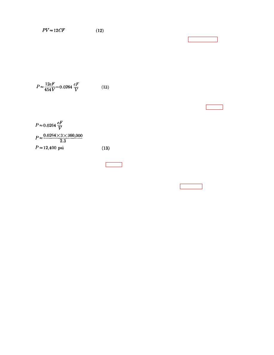
Where:
design is discussed in paragraph 45.
P=maximum gas pressure (psi)
b. The next consideration is the envelope of the
V=volume (in.3)
stroking device. The envelope dimensions may be
C=charge weight (lb)
specified with a complete drawing or only a few
F=the impetus of the propellant (ft-lb/lb)
maximum dimensions may be given. In the latter case,
The factor 12 is used to permit the use of inch units in
the designer determines all dimensions. The designer
the gas law.
Rewriting equation (12) using the
now positions the trunnions on the envelope according
equivalents indicated, and introducing a factor (454) to
to the eventual installation of the device. (The purpose
permit the charge to be given in grams, yields
of using trunnions for mounting is to permit self
alignment; and thus avoid bending loads in stroking
devices.) With all of the above completed, it is then
d. To illustrate the use of this equation, assume an
determined whether the envelope will permit the
initiator is to be designed with an internal volume of 2.3
necessary stroke. Thrusters have been developed with
cubic inches. The ballistician determines that 3 grams
as many as 3 moving tubes (fig. 25) to reconcile the
of propellant of F=360,000 ft-lb/lb is required. Applying
necessary stroke with the specified envelope.
equation (13),
c. It is now possible to compute the initial volume
(available to the powder gases) and the final volume
(the volume at end of stroke or where the tubes
separate) and determine the expansion ratio. The
expansion ratio of a device is the ratio of the final
volume to the original volume. It is customary in
propellant actuated devices to limit the expansion ratio
Since the maximum pressure which can be produced is
to 3 to 1, although several devices have had ratios
12,400 psi, this value and the value of Y corresponding
greater than 4 to 1.
to the material may be used in the curve (fig. 23) to
d. In an effort to enlarge the initial volume of a
determine the wall ratio and, therefore, the thickness of
device (and therefore reduce the expansion ratio), many
the wall.
devices are designed with holes in the walls of the inside
e. It is common practice to fabricate the first model
tubes to permit gas to flow around the tubes as well as
of a device (workhorse model) out of steel and to make
within the tubes. Figure 25 shows a thruster with this
it considerably stronger than necessary so that the
design feature. Gas flowing outside as well as within the
operation of the device and the actual pressures which
tubes also eliminates large pressure differentials and
are generated can be studied. This workhorse model
permits the inside tube walls to be made thinner and
also permits repeated firings whereas the final product,
lighter.
in most cases, is designed as a one-shot item.
e. Ballistics, in conjunction with the design, now
Considerable fabrication cost and time may be saved by
determines the charge and cartridge sizes necessary.
the liberal use of removable portions on original test
These determinations are critical for devices using
models of propellant actuated devices. These portions
pyrotechnic delay elements, since the delay elements
can be removed and modified without necessitating
must fit inside the cartridge case with the propellant.
redesign of the complete device.
The maximum pressure to be developed is also
35. Stroking Devices. a. The design procedure for
determined. If the device is to bypass pressure at the
stroking devices is more complex than that for gas
end of stroke, it must be insured that sufficient energy
generators. After the design requirements have been
remains in the device after completing its stroke to
examined and the stroke length and stroke time
permit the proper energy bypass.
approximated, it must be decided whether to use an
f. The next step is to fit a firing mechanism to the
open or a closed system and whether or not to use a
device and design the individual components. Any
damper to control the stroke. (A closed system is
changes in design that are necessary are made, and a
33


