Table VII. Comparative Data for Ejectors
Weight of
Ejected
Maximum
Method
device (lb.)
Weight
Length
velocity
of
Stroke
(lb)
(in)
(fps)
initiation
(in)
T1E1 ................................................................
1.0
0.3
5
125
Mechanical
5.0
T7 ....................................................................
2.0
1.0
6
340
Gas
3.0
T8† ..................................................................
2.6
1.0
5.5
375
Gas
3.0
T9† ..................................................................
2.6
1.0
5.5
375
Gas
3.0
T10† ................................................................
2.6
1.0
5.5
375
Electrical
3.0
T11† ................................................................
2.6
1.0
5.5
375
Electrical
3.0
† These units differ only in the mounting angle of the base plates.
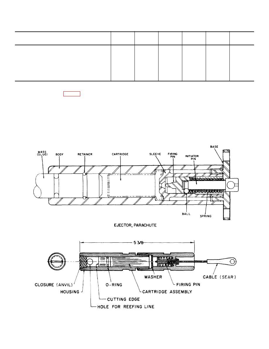
propellant gas propels the cutter blade forward. The
mechanically initiated. (Fig. 8 shows a typical reefing
blade shears the reefing line, passing through the hole
line cutter.) The firing mechanism of the reefing line
in the end of the cutter. A whole family of cartridges has
cutter is attached by lanyard to the shroud of a
been developed to provide different delay times (2-, 4-,
parachute. When the shroud lines are pulled taut by the
6-, 8-, and 10-second delays). The sear-type firing
opening parachute, the cable (sear) is pulled out of the
mechanism may be operated by pulling the cable (sear)
end of the cutter, cocking and releasing the firing
from any angle up to and including 180 to the cutter
mechanism. The firing pin strikes the primer in the
main axis.
cartridge which ignites a delay element.
After a
predetermined delay, the cartridge is fired and the
Figure 7. Parachute ejector.
Figure 8. Typical reefing line cutter.
10


