TM
3-6665-316-12
REPLACEMENT O F R E C E I V E R I N M 4 3 A 1 D E T E C T O R ( c o n t i n u e d )
4-15.
Release four latches holding receiver to case-top assembly.
9.
Disengage four latches from-four catches on case-top assembly.
NOTE
Be
sure M43AI Interface Cable
does
not
catch
on
any part of receiver.
10.
Pull up
on detector carrying handle
until
detector
internal
com-
ponents
clear rim of receiver ring.
11.
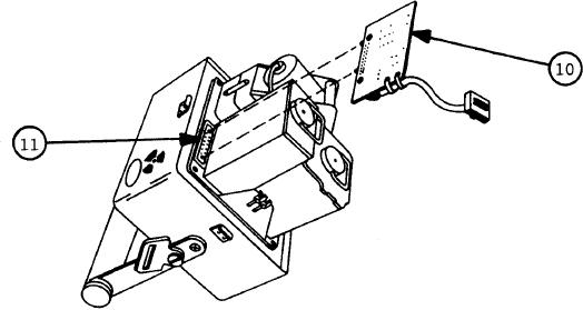
Position case-top assembly so word CAUTION and black radiation-
hazard symbol are up, internal components point up at angle to your
right, and case-top assembly rests on carrying handle and top edge of
one face of case-top assembly (as shown).
12.
Locate M43A1 Interface Cable
(10)
attached
to
case-top
assembly
at
Test Connector J10 (11).
13.
Grasp M43A1 Interface Cable and pull out until pins on M43A1
Interface Cable connector clear holes on Test Connector J10.
14.
P o s i t i o n casebottom assembly so that USUAL RESERVICING INSTRUCTION
p l a t e i s toward you.
Position case-top assembly above case-bottom
assembly so that the words 24 VDC INPUT and AIR FILTER are toward
you .
15.
Lower case-top assembly until
its
bottom
surface
contacts
top
sur-
face of case-bottom assembly.
16.
Engage four latches on case-bottom assembly with catches on
case-top
Push down on latch-locking tabs to lock latches.
assembly.
4-28

