TM
3-6665-316-12
Lower case-top assembly until bottom surface contacts top surface
of
13.
receiver ring, ensuring M43A1 Interface Cable board is properly
seated in interface cable retainer.
Engage four latches on receiver ring with four catches on case-top
14.
assembly.
Push down on four locking tabs to lock latches.
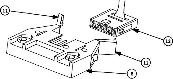
Push two catches (11)
on connector P1 (8) on decoder printed wiring
15.
Line
up M43A1 Interface Cable Connector J1 (12)
assembly apart.
with Connector P1.
Push M43A1 Interface Cable connector onto Connector P1 until catches
16.
on Connector P1 close on back of M43A1 Interface Cable connector.
Push two catches together until they snap into straight-ahead posi-
tion.
Carefully tuck excess cable into receiver ring so that no
part of cable sticks out.
Position case-bottom
assembly
so
USUAL
RESERVICING
INSTRUCTION
plate
17*
is toward you.
Position case-top assembly and receiver assembly above casebottom
18.
assembly.
The words 24 VDC INPUT and AIR FILTER should be toward
you .
Lower receiver until bottom surface
of
receiver
ring
contacts
top
19.
surface of case-bottom assembly.
20.
Engage four latches on case bottom assembly with four catches on
Push down on latch-locking tabs to lock latches.
receiver ring.
NOTE
Do not connect extender cable connector to
M43A1 Detector 24 VDC INPUT connector until
so
instructed.
4-31

