
TM 3-4230-209-30&P
2-56
2-16. PUMP UNIT SUBASSEMBLY (CONT).
REMARKS
ACTION
LOCATION/lTEM
REASSEMBLY (CONT)
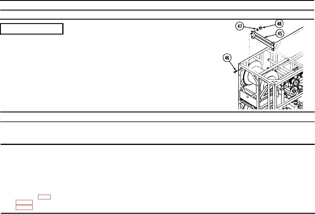
Position fairlead assembly (45) inside frame and aline slots to mate with
Pump Unit Subassembly/
the holes in frame. Insert four machine screws (46) through holes and slot
Fairlead assembly (45)
on fairlead assembly (45) and secure with flat washers (47) and hexagon
Machine screws (46)
self-locking nuts (48). Repeat for remaining fairlead assembly.
Flat washers (47)
Hexagon self-locking
nuts (48)
2-17. OUTLET HOSE ASSEMBLY.
This task covers:
c. Reassembly
a. Disassembly
b. Repair
INITIAL SETUP
Equipment Condition
Tools and Special Tools
Outlet hose assembly is removed from pump unit subassembly. See para-
Automotive Maintenance and Repair Field Maintenance
graph 2-16 for procedures to disassemble/reassemble.
Shop Equipment, Basic, Less Power (SC 4910-95-CL-A31)
Strap band clamping tools (P38)
Materials/Parts
Adhesive (item 1, app C)
Hose (fig D-26)
Hose (fig D-27)