
Pump Unit Assembly/
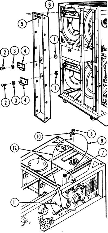
Remove two hexagon head self-locking nuts (1), two machine screws (2),
Hexagon head self-locking
and two flat washers (3) securing gun bracket (4). Repeat procedures for
nuts (1)
removal of other gun bracket. Remove 14 thread tapping screws (5) and
Machine screws (2)
remove shell (6).
Flat washers (3)
Gun bracket (4)
Thread tapping screws (5)
Shell (6)
Remove nut (7) from top screw of the vacuum gage and nut (8) from the
Nut (7)
center stud of the fuel quantity transmitter. Remove wire (9). Reinstall
Nut (8)
nuts (7 and 8) to their proper locations and tighten.
Wire (9)
Remove machine screw (10) with lock washer from fuel quantity transmit-
Machine screw (10)
ter flange. Disconnect screw (11) in TB1 -G and remove wire (12). Reat-
Screw (11)
tach machine screw (10) with lock washer and screw (11) and tighten.
Wire (12)
TM 3-4230-209-30&P
2-33