TM 3-4230-209-30&P
2-32
2-13. CLEVIS AND EYE BOLT ASSEMBLY (CONT).
REMARKS
ACTION
LOCATION/lTEM
Clevis and Eye Bolt Assembly/
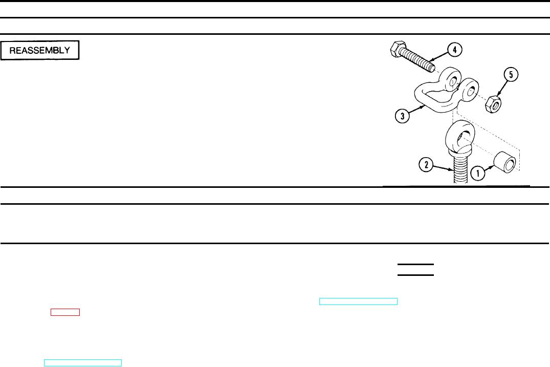
Insert spacer (1) into large hole in eye bolt (2). Saddle shackle (3) over eye
Spacer (1)
bolt (2), and aline hole in shackle (3) with hole in spacer (1).
Eye bolt (2)
Shackle (3)
Insert new bolt (4) through holes and screw on new nut (5). Tighten nut (5)
Bolt (4)
on bolt (4) snug but not tight. Tack-weld nut (5) to bolt (4) after reassem-
Nut (5)
bly is complete.
Paint clevis and eye bolt assembly with polyurethane coating after
welding.
2-14. PUMP UNIT ASSEMBLY.
This task covers:
c. Reassembly
a. Disassembly
b. Repair
Special Safety Instructions
INITIAL SETUP
Tools and Special Tools
WARNING
Automotive Maintenance and Repair Field Maintenance
Negative battery cable must be disconnected from the battery any time that
Shop Equipment, Basic, Less Power (SC 491 0-95-CL-A31 )
the control panel assembly is being removed or is removed from the pump
unit. See TM 3-4230-209-20&P.
Materials/Parts
Ground wire (fig D-16)
Battery and battery compartment area may be coated with acid due to
Transmitter wire (fig D-17)
spillage and/or fumes. Wear protective clothing when working in this area.
Equipment Condition
Before eating, smoking, or touching your face or clothing, wash your hands
Engine and pump unit protective cover and pump unit panels are removed and
with a solution of baking soda and water, then flush them with clear water.
fuel is drained from fuel tank. Unit maintenance authorized components are
If battery acid gets into your eyes, flush them with clean water. Obtain
removed in TM 3-4230-209-20&P and are not covered in this manual.
medical treatment immediately. Failure to do so may cause blindness.

