TM 10-5410-228-24
(4)
Position cable in correct routing location using care to avoid sharp edges and areas where the
cable could be damaged or pinched. Secure in place with new tie-down straps.
(5)
Install two clamps (16) on cable assembly A17W1. Secure two clamps (16) to ECV dash with two
screws (13), two new lockwashers (14) and two flat washers (15).
(6)
Secure cable assembly 1A4W4 connector J1 to pan and frame with four nuts (9), four new
lockwashers (10), four flat washers (11) and four screws (12).
(7)
Connect 1A4W4 connector P1 to J2 on control box assembly.
(8)
Secure cable assembly 1A4W1 connector J1 to pan and frame with four nuts (5), four new
lockwashers (6), four flat washers (7) and four screws (8).
(9)
Connect 1A4W1 connector P1 to J9 on back of rear control panel.
(10) Secure cable assembly 1A4W3 connector J1 to pan and frame with four nuts (1), four new
lockwashers (2), four flat washers (3) and four screws (4).
(11) Connect 1A4W3 connector P1 to J8 on back of rear control panel.
(12) Connect 1A4W25 connector P1 to J2 on radio speaker assembly.
(13) Secure cable assembly 1A4W25 connector J1 to pan and frame with jam nut.
(14) Connect 1A4W23 or 1A4W24 connector P1 to J1 on radio speaker assembly.
(15) Secure cable assembly 1A4W23 or 1A4W24 connector J1 to pan and frame with four nuts (9),
four new lockwashers (10), four flat washers (11), and four screws (12).
(16) Connect cable connectors 1A1W1P1, 1A1W2P1, 1A1W3P1, 1A4W18P1, 1A4W19P1, and
1A4W20P2.
(17) Turn on system power and verify system functions correctly.
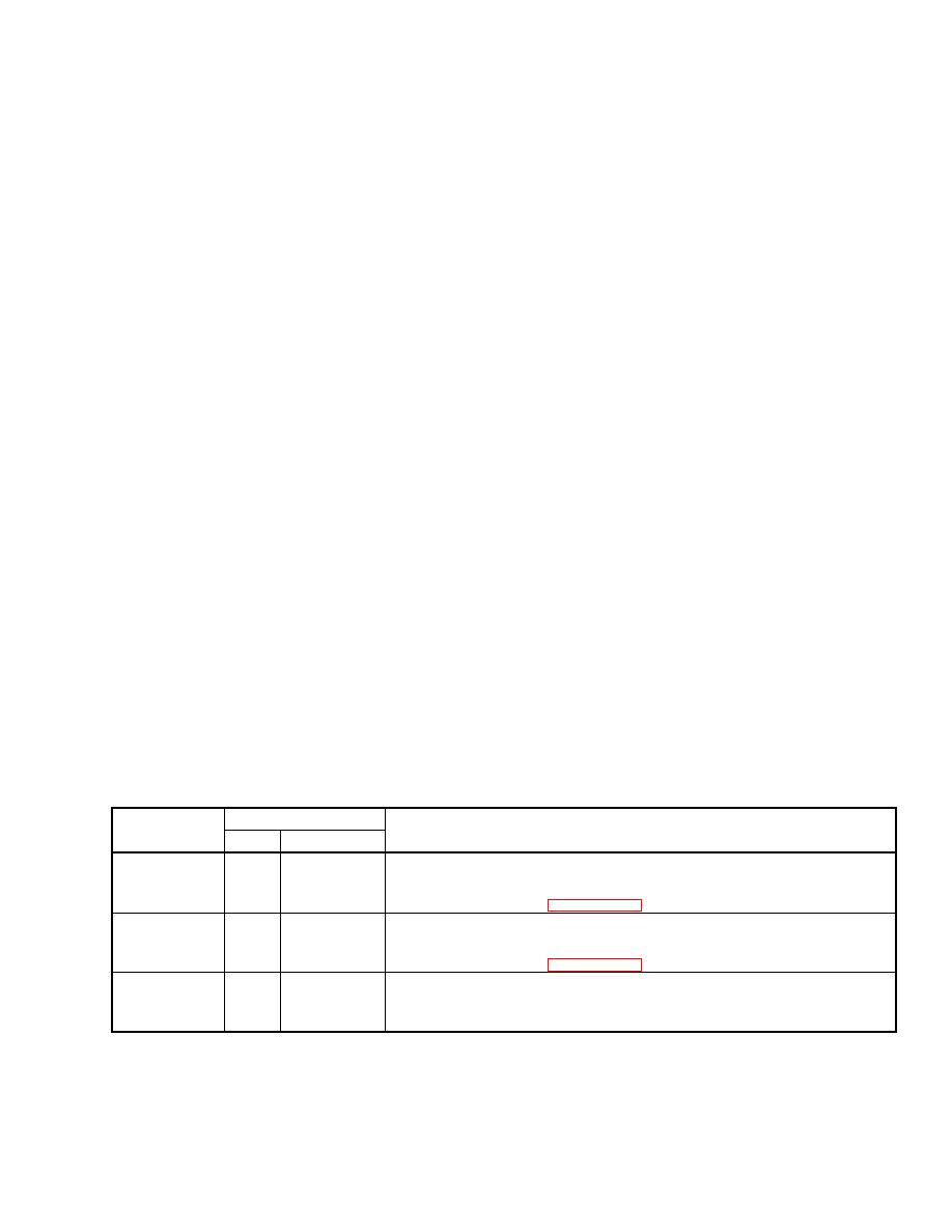
2.13.27.2 Cables in ECU.
a. General
The following table contains information necessary to remove and replace cables. The headings found
in the table are described as follows:
(1)
Cable No. The W number found on the cable is listed in this column.
(2)
Connectors. Under the connectors column is a listing of each connector on the cable and its
mating location.
(3)
Comments. This column contains additional information that could help in the removal or
installation of the cable.
Connectors
Cable No.
Comments
No.
Mates to
1A4A1W1
J1
1A4W6P1
Connected to cable 1A4A1W3 connector P1 in ECU and cable 1A4W6
J3
1A4A1W3P1 connector P1 through LMS and ECU access opening (behind forward
control panel, refer to para 2.13.16).
1A4A1W2
J2
1A4W2P2
Direct wired to ECU electric heaters and connected to cable 1A4W2
ECU electric connector P2 through LMS and ECU access opening (behind forward
heaters
control panel, refer to para 2.13.16).
1A4A1W3
P1
1A4A1W1J3 Direct wired to ECU hydraulic control and connected to cable
hydraulic
1A4A1W1 connector J3 in ECU.
control


