T.O. 33B-1-1
5-78
maximum flexure in the layer being tested, is chosen for the inspection. A typical fixed frequency is 25 kHz. The low
frequencies eliminate the need for liquid couplant between the transducer and the test part. On some instruments, a
variable time gate is used to select the part of the received pulse that has the greatest change in amplitude when the
probe is scanned from a bonded area to an unbonded area. The amplitude will be larger over the unbond versus a
bonded area because the motion of the layer is restricted over a bonded area and energy is lost into the second layer.
The pitch/catch modes work on composite delaminations, skin-to-core unbonds, metal-to-metal unbonds and skin-to-
core disbonds. The method tends to lose its effectiveness if the material thickness between the probe and the
disbond/delamination exceeds 0.08 inch of aluminum or 0.30 inch of nonmetallic composite. In addition, the
minimum dimension of a detectectable flaw is greater than or equal to the probe tip spacing.
5.4.6.3
Pitch/Catch Swept Frequency Method.
Instead of a single frequency, each pulse contains a range of frequencies, for example, 20 to 40 kHz or 30 to 50 kHz.
Ultrasonic plate or Lamb waves are generated in the part. These waves are attenuated by coupling into the second layer
in well bonded joints. In an unbond region the waves travel with very little attenuation or leakage into the second layer
and produce larger indications. Both the swept and impulse techniques will find similar types of defects. However,
with the swept technique, calibration interpretation of the signals may be easier because both the amplitude and phase
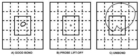
signals are simultaneously displayed in the form of circular patterns on one X-Y active screen. Figure 5-78 shows
instrument displays corresponding to three situations detected with the Pitch/Catch Swept-Frequency Method.
Figure 5-78. Pitch/Catch Swept-Frequency Signal Patterns.
5.4.6.4
Mechanical Impedance Analysis (MIA) Method.
The driver portion of a single-tip dual-element probe generates low-frequency sound waves that transfer to mechanical
movements in the test material. The stiffness and mass of the material are measured by the receiving sensor and
displayed in terms of both phase and amplitude values. The receiver element at the bottom of the probe has its loading
affected by the part stiffness which changes from very high over bonded regions to low over unbonded regions. Since
the measurements are a comparison of stiffness, results are better on stiff structures. Flexible composites would not
have much change in stiffness from bonded to unbonded areas. The MIA mode does not require couplant and has a
small contact area so it can be used on irregular or curved surfaces. The MIA technique seems most suitable for
detecting damage associated with honeycomb core such as skin-to-core disbonds severely corroded aluminum core, and
buckled or crushed core. However, disbonds and delaminations also can be detected with this method. Figure 5-79
shows typical positions of indications produced with the MIA method. During an inspection only the "flying" spot
would be present on the display. The gate box can be positioned anywhere on the display; the appropriate position is
determined during calibration. Figure 5-80 illustrates an instrument that is capable of operating in all four modes
(resonance, pitch/catch impulse, pitch/catch swept-frequency and mechanical impedance). The alignment problem is
normally solved be gridding off the inspection area and keeping the inspection area down to a manageable size. If the
area is very large special fixtures are normally manufactured to hold both transducers and keep them aligned.


