T.O. 33B-1-1
5-76
5.4.6
Methods Associated With Instruments Dedicated to Bond Inspection.
Refer back to the bottom half of Table 5-6 for a summary of these methods, which are described in detail below.
5.4.6.1
Resonance Method.
An appropriate ultrasonic contact probe is placed on a test sample with couplant and is driven at its resonance
frequency by an oscillator in the instrument. The detector in the instrument measures the phase and amplitude
components of the electrical impedance of the probe, which are affected by changes in the acoustic impedance of the
test part. The acoustic impedance of a part is altered by a lack of bond or a delamination. Bonded laminates act like a
thin plate, which vibrates and generates a standing wave. Changes in the effective thickness caused by the unbonds or
delaminations will significantly affect the phase and amplitude of the acoustic wave in the part. With the resonance
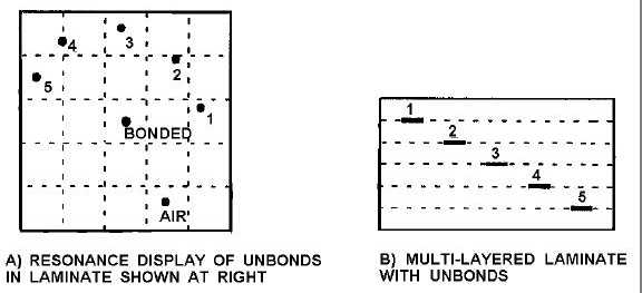
method the instrument indicates the probe's impedance with a "flying" spot on an ultrasonic impedance plane display.
Amplitude changes in impedance are indicated by the radial distance of the spot from the center of the display (null
reference point), and changes in the phase are indicated by the rotation of the spot around the center null point. Figure
5-75A is an example of an ultrasonic impedance plane display which shows the spot positions corresponding to
different depths of unbonds (delaminations) in the bonded laminate in Figure 5-75B. The laminate is an example of a
typical reference standard that would be used for calibration. The positions can be gated, so that a disbond produces an
alarm, or the display can be monitored to determine between which layers a disbond occurs. The resonance mode
works very well for detecting disbonds at metal/metal, metal/composite and composite/composite interfaces, for finding
delaminations within composite materials, and for detecting skin-to-core disbonds in honeycomb sandwich structures.
Figure 5-75. Resonance Method.
5.4.6.2
Pitch/Catch Impulse Method.
A pulse of a single ultrasonic frequency is transmitted into the part by one while a second transducer, mounted about
3/4 inch away in the same probe assembly, receives the returned signal. Contact with the part is made through 1/4-inch
diameter nylon wear tips on spring-loaded metal rods attached to the respective transducers. The ultrasound travels
through the material between the two probe tips. The received signals are displayed in various ways depending on the
instrument: a) amplitude and phase components are displayed on separate meters, b) the resultant signal activates light-
emitting-diode (LED) display or c) the phase and amplitude components are combined to position a "flying" spot on an
impedance plane display. The first type of display is the old style used on the Sondicator, The box in the middle of the
display in Figure 5-76 is the gate that sets off an alarm if the spot lands inside, indicating a disbond.


