T.O. 33B-1-1
5-14
5.1.6.2.5
Beamspread.
In the near field the sound beam propagates straight out from the face of the search unit. In the far field the sound
beam spreads outward and decreases in intensity with increasing distance from the central axis of the beam, as shown
in Figure 5-13 At a given frequency, the larger the transducer element, the straighter the sound beam, and the smaller
the transducer element, the greater the beamspread. Also there is less beamspread for the same diameter transducer
elements at higher frequencies.
The half angle of the beamspread q (theta) is calculated as follows:
sin
q =
1.22l
D
Where:
l = wavelength (inches)
D = transducer diameter (inches)
Example: Given 2014-T4 aluminum being tested with a ¼-inch diameter unit at 5 MHz, what is the half
angle of the beam spread?
D = ¼ inch (0.25 inch)
l = 0.049 inch (from Table 5-1)
sin
( .
).
.
.
q =
=
1
220049
0
25
0
2391
q = 14° (from Table 5-1)
5.1.6.2.5.1
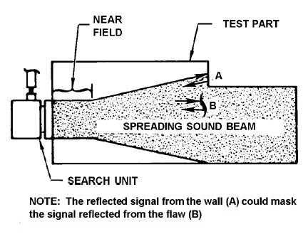
Beam spread is important to consider, because in certain inspection applications the spreading sound beam can reflect
off of walls or edges and cause confusing signals on the A-scan presentation. For example, see Figure 5-14.
Figure 5-14. Example of Beam Spread Causing Confusing Signals.


