T.O. 33B-1-1
5-15
5.1.6.2.5.2
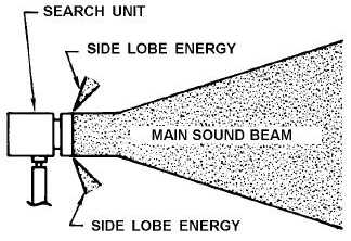
In addition to the main sound beam pattern discussed above, there is also a small amount of side lobe energy, as shown
in Figure 5-15. Some of the effects of this side lobe energy are discussed in paragraphs 5.1.7.1 and 5.3.6.5.3. Due to
side lobes, the efficiency of a transducer is reduced, and the actual useable width of a sound beam near the face of the
transducer is less than the physical width of the piezoelectric element.
Figure 5-15. Main Sound Beam and Side Lobe Energy.
5.1.6.2.6
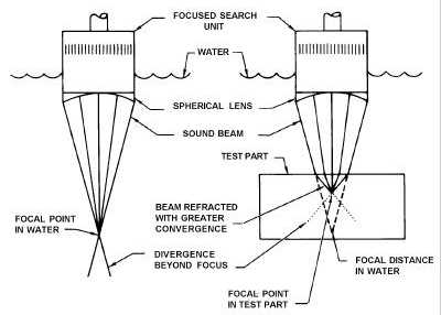
Focused Sound Beams. On some immersion inspections or special contact tests with a water delay column, a focused
sound beam is used (see Figure 5-33). As shown in Figure 5-16, the focusing is produced by using a search unit
containing a plastic acoustic lens on the face of the transducer element. The acoustic lens causes the sound beam to
converge as the sound travels away from the transducer. Due to refraction at the plastic-water interface, a peak in
amplitude is obtained at the focal point. The amplitude decreases rapidly on each side of this point. This type of search
unit has a high sensitivity for discontinuities located at the focal point distance due to the concentration of energy at
this focal point, but the depth of material that can be inspected in any one scan is limited. Beam shaping, which "tucks
in" the side lobes can also be accomplished by using an acoustic lens without creating a focused transducer.
Figure 5-16. Focused Sound Beams


