T.O. 33B-1-1
4-20
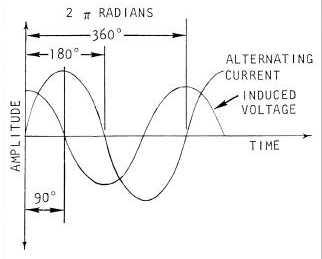
Figure 4-14. Sinusoidal Variation of Alternating Current and Induced Voltage in a Coil
4.3.2.3
Combining Out Of Phase Quantities.
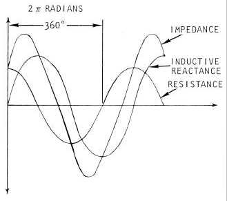
A real coil has a resistive component of the impedance in addition to the inductive reactance. They can be combined to
describe the net impedance. A coil can be considered to be a resistor in series with an inductor. Applying an
alternating current to this series circuit will result in two voltages, one across the resistor and another across the
inductor. The net voltage across the combination of the resistor and inductor, i.e. across a real coil, will be the
combination of the two voltages. The voltage across the resistor will be in phase with the current while the voltage
across the inductor will lead the voltage across the resistor by 90 degrees. The combination of the two voltages, as
illustrated in Figure 4-15, results in a voltage that will be out of phase with the current but not by a full 90 degrees.
Figure 4-15. Combining of Out-of Phase Voltages
4.3.2.3.1
X-Y Plot Representation.
Another way to illustrate the combination of out-of-phase quantities in a coil is illustrated in Figure 4-16. Here the two
voltages drop; one across the resistor (VR) and the other across the inductor (VL) are plotted at right angles to each


