T.O. 33B-1-1
4-17
4.3.1.2
Signal Detection.
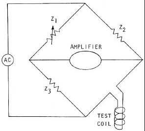
A simple but effective signal detection technique is to use a bridge circuit as illustrated in Figure 4-12. With current
flowing through the test coil and the coil positioned on a flaw-free or reference area, the variable impedance Z1 can be
adjusted so that zero current flows through the amplifier. This adjustment is termed either “balancing” or “nulling” the
bridge. When the coil is placed on a flawed or damaged area, the resultant change in current through the coil
“unbalances” the bridge and current flows through the amplifier. This current is the inspection signal. The signal has
the same frequency as the current through the coil. The phase and amplitude of this signal contains information on the
condition that caused the bridge unbalance.
Figure 4-12. Simplified Bridge Circuit
4.3.1.3
Signal Analysis.
In the simplest type of instrumentation, analysis of the signal consists of measuring the change in magnitude of the
current flowing through the bridge. Changes in the magnitude of the alternating current are amplified and converted to
a direct current for display or readout. In more sophisticated instrumentation, both amplitude and phase are measured
4.3.1.4
Displays.
The method by which eddy current signals are presented is dictated by the type of information required and the
complexity of the instrumentation. When only signal amplitude is measured, meters, alarm signals, or recorders are
commonly used. When both amplitude and phase information are to be displayed, a cathode ray tube or some other two
dimensional display device is normally used.
4.3.1.4.1
Amplitude Display.
Meters may be analog (needle moving over a fixed numerical scale) or digital. Audible or visual alarms may be set to
trigger when the signal amplitude exceeds a predetermined threshold. A recorder presents a continuous record of the
signal amplitude during an inspection for subsequent analysis.
4.3.1.4.2
Impedance Plane Display.
Defects or other variations in material characteristics will alter the strength and distribution of an induced eddy current
flow. Changes in the eddy current flow will result in changes in the inducing coil or sensor coil currents. These
changes can be expressed as an apparent change in the coil’s electrical impedance. This makes it possible to associate
changes in material properties with specific changes in the apparent impedance of either the excitation or sensor coils.
The two-dimensional display that permits this is the most commonly used and is called an impedance plane display.
The usefulness of impedance plane displays will be discussed later starting with paragraph 4.3.2.5.