T.O. 33B-1-1
3-15
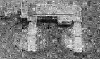
Figure 3-18. Electromagnetic Probe or Yoke
3.1.9.9
Alternating Current (AC) Yoke.
Alternating current, which is single phase when used directly for magnetizing purposes, usually has a frequency of 50
or 60 Hertz. The AC longitudinal magnetizing field induced in the part is restricted to the surface due to its skin effect.
AC provides a very desirable field for maintenance and overhaul inspection work due to it’s high sensitivity to surface
defects. The peak AC current produces a surge peak in the magnetic field that is well above the average DC current
required to develop a field of equivalent strength.
3.1.9.9.1
AC magnetic fields form eddy currents that tend to guide or restrict the magnetic lines of flux into a narrow pattern
between the poles. Another by-product is a vibratory action at the work piece, which adds mobility to the inspection
particles to form larger and more distinct build up of particles at the defect.
3.1.9.9.2
An AC magnetic field can be used when it is necessary to discriminate between surface indications and subsurface
defects that might be revealed with a DC magnetizing field. Yokes utilizing AC magnetization also have the additional
advantage that they can be readily used for demagnetization.
3.1.9.10
Direct Current (DC) Yoke.
An electro-magnet powered by DC provides a very strong magnetic field. However, being a constant field and lacking
any vibratory action, it is sometimes difficult to gather enough particles at the defect to form a visible indication. To
overcome this difficulty, full-wave or half-wave rectified single-phase alternating current is used. This adds mobility to
the magnetic inspection particles comparable to that produced by AC.
3.1.9.11
Permanent Magnet Yoke.
Permanent magnets can be used to magnetize parts for MPT. This method of magnetization has severe limitations and
is properly used only when these limitations do not prevent the formation of satisfactory leakage fields at
discontinuities.
3.1.9.11.1
Permanent magnets create longitudinal fields. The poles created on the parts can result in confusing particle
indications. Control of field direction is possible only over a limited area. A permanent bar magnet, set on end on the
surface of a steel plate, creates a radial field in the plate around the pole at the end of the bar as shown in Figure 3-19.
The flux of this field leaves the plate surface at some distance from the point of contact to return to the pole at the
opposite end of the magnet. Cracks crossing such a field pattern can be indicated provided the field produced in the
plate is sufficiently strong. When the poles of a permanent magnet yoke are placed upon the surface of a steel plate or
part, the field travels through the object from one pole of the yoke to the other. The flux generally follows along a
straight line drawn between the poles, and is strongest near the poles of the yoke and weakest at the point midway
between the poles. The magnetic field strength within the part depends on the strength of the yoke magnetization and
the distance between the poles. Cracks at right angles, or nearly so, to this line can be indicated, provided the field


