T.O. 33B-1-1
3-17
3.1.9.12.2
Multidirectional Magnetization.
Complex-shaped parts can be sometimes inspected rapidly with equipment capable of producing magnetic fields in two
mutually perpendicular directions in rapid succession. For large parts such as shipyard castings, the equipment
produces three phase full wave rectified AC and rapidly switches it between several different magnetizing modes. An
alternate approach, used for smaller parts, is to use each of the three phases, either rectified or unrectified, for a
separate magnetizing mode. Such equipment can then apply up to three magnetizing modes in rapid succession to a
part.
3.1.9.12.2.1
The multidirectional units produce the multidirectional magnetization effect by rapidly changing the magnetizing
directions. For equipment utilizing the switched mode of operation, the switching can be on the order of 0.1 seconds.
For the other type of equipment, the magnetizing modes are out of phase by 120 degrees. For 60-Hertz current this is
equivalent to switching magnetization directions in less than 0.006 seconds. These units are capable of producing
indications of discontinuities with widely differing orientations in a single operation, thus saving the time to conduct
two or more separate inspections with different magnetic field excitation setups. It is not possible to estimate the
required magnetizing currents before hand to produce the required magnetic field strengths and directions.
Consequently, sensors must be used to determine the resulting strength and orientation of the magnetic fields in order
to develop valid inspection techniques with multidirectional magnetization methods.
3.1.9.12.3
Induced Current Magnetization.
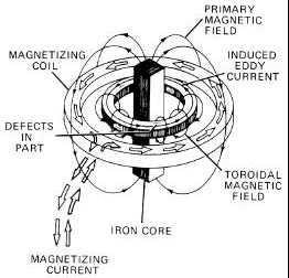
When inspecting ring-like parts for defects in a circumferential direction, the induced current technique can sometimes
be used to good advantage. As an example, a ring-shaped part is placed inside and concentric to a magnetizing coil
being excited with AC (see Figure 3-20). A laminated ferromagnetic core is placed inside the part and parallel to the
axis of the coil in order to concentrate the magnetic field. The time-varying AC induces eddy currents in the test piece,
which in turn induce a circular magnetic field within the test part. Such a field is used to detect circumferential defects
within the test part.
Figure 3-20. Current and Field Distribution in a Bearing Race being magnetized by the Induced Current
Method
3.1.9.12.3.1
The core piece used should be laminated and made of low retentivity iron. If the part is ring-shaped, the core length
should be approximately equal to the ring diameter or longer, but never less than six inches, and must be centered in
the part. For a disc-shaped part with no bore, shorter core pieces should be placed on either side of the disc so that they
are parallel to the axis of the part. In some cases it is advantageous to shape the ends of the core pieces adjacent to the
part to facilitate bath application. Since the induced current method does not require contacting the part, there is no
danger of local part overheating.


