T.O. 33B-1-1
3-8
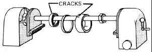
Figure 3-12. Using a Central Conductor to Circularly Magnetize Ring-Like Parts.
3.1.6.7
Longitudinal Magnetization.
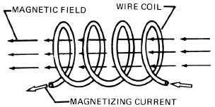
Electric current can also be used to create a longitudinal magnetic field in a test part with a current carrying encircling
coil. Application of the right hand rule to any segment of a coiled conductor will show that the field within the coil
consists of contributions from each turn of the coil and is aligned lengthwise as indicated as shown in Figure 3-13.
Figure 3-13. Magnetic Lines of Force (Magnetic Field) in a Coil.
3.1.6.7.1
In Figure 3-14a. If a part is placed inside a coil; the magnetic lines of force created by the coil are aligned along the
longitudinal axis of the coil. If the part is ferromagnetic, the high permeability concentrates the lines of flux within the
part and induces a strong longitudinal magnetic field.
3.1.6.7.2
Longitudinal Magnetization with Inspection Equipment.
Inspection of a cylindrical part using longitudinal magnetization is shown in Figure 3-14b. When a transverse
discontinuity exists in the part, as in the illustration, a magnetic leakage field is formed at the crack location. This
attracts magnetic particles, forming an MPI indication of the transverse discontinuity. Compare Figure 3-14b with
Figure 3-10, and note that in both cases, a magnetic field has been induced in the part that is at right angles to the
defect. This is the most desirable condition for reliable inspection.
Figure 3-14a. Longitudinal Magnetic Field Produced in a Part Placed in a Coil.


