W=propelled weight (pounds)
k=a constant (6.25X10⁻⁵ for catapults and 5.38X
(2)
10-5 for removers)
Where a is the maximum rate of change of
v=terminal velocity (fps)
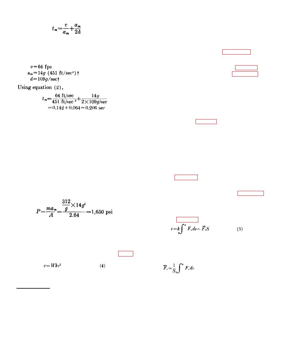
acceleration. The use of equation (2) is demonstrated
(2) Equation (4) is a simplification of equation
by the following calculation which was made to
(31) presented in Chapter 5.
The
determine the stroke time of the M5 catapult. The M5
derivation of the constants used in
catapult has the following performance characteristics:
equation (4) is presented in "Refinements
to First Order Equations," in Chapter 5.
(3) To use the curves of figure 21 in
approximating the propellant charge in a
catapult (the M5 catapult for example)
find the intersection of the terminal
velocity (64 fps) abscissa and the catapult
curve. The ordinate of this point (0.26
gm/lb) is the ratio of the charge weight to
the propelled weight. Since the propelled
weight is 312 pounds, multiply the ratio
The stroke for the M5 catapult actually is 0.220 seconds.
found in figure 21 by 312 pounds and the
22. Peak Pressure. a. The relationship between peak
approximate charge weight is found to be
pressure, P, and piston area or tube area, A, may be
81 grams. This is a reasonable estimate
estimated by using Newton's Law (F=ma) and
since the actual charge weight of the M5
substituting PA for force, F, where m is the propelled
catapult is 84.5 grams.
(4) A similar procedure is followed when
PA=mam
(3)
estimating the charge weight of a
Equation (3) may be used to determine the piston or
remover, except the remover curve is
tube area if a specific pressure is desired, or it may be
used.
used to determine the peak pressure if the area is
b. Thrusters.
established.
(1) Figure 22 is used, in a manner similar to
b. The characteristics of the M5 catapult are used
that outlined above, to estimate the
again in the following calculation as an example of how
propellant charge for a thruster. Two
to use equation (3). The propelled mass is 312/g slugs
curves are presented in figure 23,
and the tube area is 2.65† + square inches. Therefore:
showing two groups of propellants of
different impetus which are used in
stroking devices. The curves are plotted
from equation (5) which is derived in
The actual peak pressure in the M5 catapult is 1800 psi.
23. Propellant Charge Weight. a. Catapults and
Removers.
Where:
c=charge weight (grams)
(1) A first order design approximation of the
k=a constant (based on the propellant used)
propellant charge weight for catapults and
removers may be found by using figure
Fr=resistive force (pounds)
21. This figure is based on the equation:
S=stroke (inches)
Where:
c=charge weight (grams)
† Refer to footnote on page 24.
‡ Chosen on the basis of installed dimensions and dimensions) of standard tubing.
Different constants are used for catapults and removers since the characteristic propellant composition and energy losses for
these two types of devices are different.
26


