TM 5-3740-218-13&P
(7)
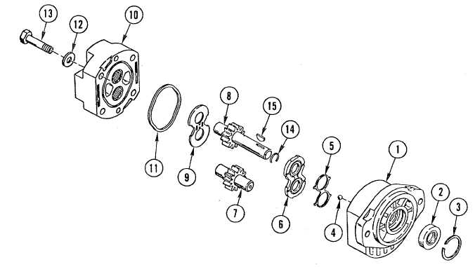
Insert sleeve into inside diameter of shaft seal (2) from front of motor until sleeve contacts drive gear
bearing. Install drive gear shaft (7). Remove drive shaft installation sleeve.
(8)
Install drive gear shaft (8) with long journal toward front of motor.
(9)
Lubricate rear gear faces and journals with SAE 10W-40 oil (item 40, Appendix E) and install thrust plate (9)
with bronze thrust surface contacting gear face.
(10)
Apply Lubriplate (item 35, Appendix E) to body (10) groove and install new square cut ring (11) into groove.
CAUTION
Maintain body in vertical position, gear bores up, during cover installation to
prevent shifting of thrust plate. Any shift of thrust plate will result in pinching
between cover and body when cover bolts are tightened.
(11)
Lubricate cover (1) bearings with SAE 10W-40 oil (item 40, Appendix E). Match matchmarkson cover (1)
with matchmarks on body (10) and install cover (1).
(12)
Position motor in arbor press, shaft end down, and press on cover (1) while installing four washers (12) and
four bolts (13). If press is not available, install washers (12) and bolts (13) and tighten evenly in cross
pattern to avoid pinching parts. When all bolts (13) are installed and cover (1) is tightened down, torque
bolts to 34-38 lb-ft (46-51.5 N.m).
(13)
Install snap ring (14) and woodruff key (15) on drive gear shaft (7).
(14)
Using adjustable wrench to turn drive gear shaft (7), verify drive gear shaft (7) turns without evidence of
mechanical bind.
5-45