TM 3-6665-329-13&P
The preceding troubleshooting procedures will detect most faults, if all the preceding checks did not
a.
uncover the fault, remove the circuit card assembly from the test set and perform point-to-point continuity checks
on the test set wiring harness listed in the following table.
Reference designations are used in the table. The following is a list of components with their reference
designation.
Reference
Location
Designation
Connector
Panel Assembly
ELECTRONICS MODULE
J1
Panel Assembly
INPUT POWER
J2
Behind Panel Assembly
Circuit Card Assembly
J3
Panel Assembly
REMOTE ALARM BOARD
J4
CABLE STORAGE compartment
P1
CHASSIS TEST CABLE
P2
DETECTOR POWER CABLE
CABLE STORAGE compartment
PUMP POWER CABLE
P3
CABLE STORAGE compartment
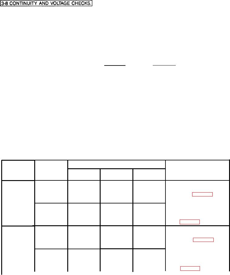
Table 3-3. Switch Continuity Checks
Measure Resistance
Set
If reading is
Switch
Switch
incorrect:
Should
Name
To
From
To
Read
P1 Pin 2
1. Test switch.
J3 Pin 6
Short
Replace defective
Short
J3 Pin 6
J1 Pin 27
INHIBIT
J1 Pin 7
switch (Para 3-31)
Short
J3 Pin 6
P1 Pin 1
Short
J3 Pin 6
2. Test for bro-
ALARM
ken switch wires.
J3 Pin 6
Open
J1 Pin 27
Replace branched
Short
J1 Pin 7
J3 Pin 6
OPERATE
wiring harness
P1 Pin 1
Short
J3 Pin 6
P1 Pin 2
Open
J3 Pin 6
J1 Pin 4
J3 Pin 13
1. Test switch.
Short
Replace defective
J3 Pin 42
J1 Pin 4
Open
ON
switch (Para 3-31)
J3 Pin 14
J1 Pin 19
Short
J3 Pin 43
J1 Pin 19
Open
2. Test for bro-
HEATER
ken switch wires.
J1 Pin 4
Open
J3
Pin
13
Replace branched
Short
J3
Pin
42
J1 Pin 4
OFF
wiring harness
J1 Pin 19
Open
J3
Pin
14
J1 Pin 19
Short
J3
Pin
43

